


INSTALLING A REMOTE EMERGENCY POWER-OFF CONTROL
EATON Powerware
®
9315 UPS (500–750 kVA) Installation and Operation Manual S 164201244 Rev E www.powerware.com
5-2
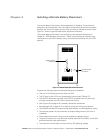
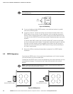
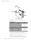
NOTE REPO switch rating is 6A/120 Vac or 3A/240 Vac. The REPO switch must be a latching-type switch
with a dedicated circuit.
REPO
Switch
Twisted Wires (2)
9
10
CUSTTB
Figure 5‐2. REPO Wiring
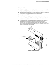
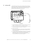
5. If you are installing multiple REPO stations, wire additional stations in parallel
with the first REPO station.
6. If required, install ½” conduit and wiring from the second contact block in the
REPO station to trip circuitry of other equipment, such as upstream protective
devices, facility monitoring devices, or alarms. Using the contact block that was
not used for the UPS EPO wiring will help maintain isolation between the control
systems.
A normally open (NO) contact and a normally closed (NC) contact are provided,
and the two are electrically isolated. If single-pole, double-throw action is desired,
one side of the NO contact can be jumpered to one side of the NC contact to
form the common connection point. REPO switch wiring must be according to
UL Class I requirements.
7. Secure the UPS by reversing all steps taken to prepare it for a REPO station
installation.ą
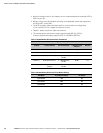
5.2 REPO Operation
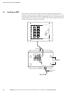
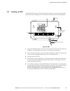
To activate the REPO switch, firmly push the red pushbutton until it locks into place.
The switch latches into the activated state.
To deactivate the REPO switch, insert the supplied key and rotate clockwise until the
red pushbutton releases. To remove the key, rotate the key back to the vertical
position.
NOTE Follow Lockout/Tagout (LOTO) procedures for your location. The key should not be stored in the
switch. Do NOT insert the key until the fault is resolved.
Deactivated
Unlock pushbutton to release
Activated
Pushbutton locked into place
Figure 5‐3. REPO Operation