


Chapter 1 Interfaces
28
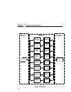
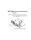
DIP Switches
ADAPTER,
WLAN
ADAPTER
On the back of the printer, you will find a small window where you
can access two DIP switches labeled 1 and 2 (see Figure 2 on
page 24). The functions of the DIP switches are explained in
Table 7.
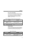
NOTE: The DIP switches are not marked with “on” or “off” labels.
Instead, the status of the switch is indicated by its position,
up or down. If the interface card has been installed upside
down (i.e., the DIP switches are to the left of the cable
connector), your DIP switch positions will be reversed and
the settings inverted.
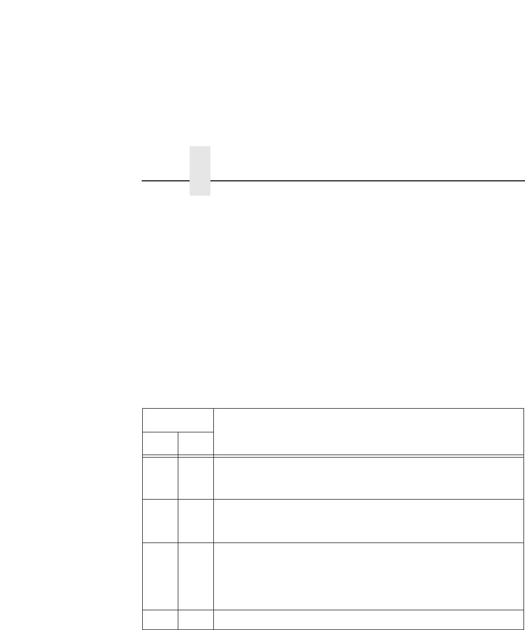
Table 7. 10/100Base-T DIP Switch Settings
DIP Switch
Comments
12
up up Normal operation. With both DIP switches in the “off” position, the
NIC boots up using the settings in flash memory rather than the
default settings.
down up Factory default. With the DIP switches in this configuration, the NIC
boots up and all settings stored in flash memory are erased except
the Ethernet address and key value.
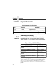
up down Default IP. With the DIP switches in this configuration, the NIC boots
up with factory default settings. However, the stored settings in flash
memory are intact. Setting DIP switch 2 to “on” does not clear any
settings stored in flash memory; it boots the unit in a different state
with the settings in flash memory temporarily ignored.
down down Reserved. This DIP switch configuration is not for customer use.