


3 – FVIC Configuration and Monitoring Features
D000003-006 Rev. A 3-25
Q
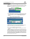
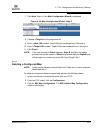
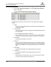
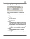
NOTE: Ports 11 and 12 of the FVIC (e.g L01P11 and L01P12) represent the ports
between the switch chip on the FVIC and one of the FVIC internal HCA
chips.
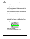
3.3.6.1
Port Statistics Field Descriptions
Link State:
Indicates whether the InfiniBand link associated with the physical port is up or down.
Possible values are no state change, down, init, armed, active, and unknown.
Physical State:
Indicates whether the internal connection to the InfiniBand port is up or down.
Possible values are No State Change, Sleep, Polling, Disabled, Training, Up,
and Error Recovery.
Link Down Default:
Indicates the default down state as set by the Fabric Manager. Possible values are
No State Change, Sleep, Polling, and Unknown.
Active Link Width:
Indicates the bandwidth of the link on the backplane. The bandwidth is specified as
a multiplier of 2.5 Gbit/sec full duplex serial links. As an example, 4X specifies a
bandwidth of 10 Gbit/sec.
NOTE:Values of 1X are possible in this field with 4X IB cables if poor cable
connections or defective 4X IB cables are used.
Link Width Enabled:
Indicates actual link width as opposed to the supported link width.
Link Width Supported:
Indicates the link width in terms of multipliers of 2.5 Gbit/sec full duplex serial links
supported by the port.
Active Link Speed:
Indicates the speed of the full duplex serial link. This is either 2.5Gbps (single data
rate, or SDR), or 5.0Gbps (double data rate, or DDR).
Link Speed enabled:
Indicates the actual link speed as opposed to the supported link speed. This could
be 2.5Gbps (SDR), 5.0Gbps (DDR) or both.
Link Speed supported:
The supported link speed of the port. This could be 2.5Gbps (SDR), 5.0Gbps (DDR)
or both.