


16 SANRAD V-Switch User Manual
V-Switch Overview
The V-Switch provides protocol bridging, routing, switching and volume
management in a single platform.
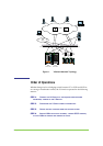
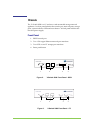
Figure 1, page 17, details a standard V-Switch network topology. Two V-
Switches sit in the center of the network, providing load balancing and
failover ability.
Above the V-Switches are IP clouds connecting the network(s) management
and host stations. The hosts can connect to the V-Switch directly or via an
IP cloud. An iSCSI initiator agent in the host allows access to virtual
volumes in the V Switch.
Below the V-Switches are the network storage devices, which include both
JBOD (Just a Bunch Of Disks) and RAID subsystems. The V-Switch
provides the ability to connect via both SCSI and FC protocols, including FC
clouds, increasing the number of potential attached storage devices.
The V-Switch can be used in two modes:
iSCSI bridging switch
Storage virtualization switch
End-to-end Fibre Channel protocol networks are expensive to implement.
As an iSCSI bridging switch, the V-Switch acts as a protocol bridge between
storage devices on a Fibre Channel network and hosts on a standard IP
network.
The V-Switch also acts as a protocol bridge between SCSI storage devices
and hosts on a standard IP network.
Simple exposure of each storage device as a single LUN is an inefficient use
of storage resources. As a storage virtualization switch, the V-Switch
enables barrier-independent storage pooling with precise LUN carving of
new virtual volumes which support mirroring and striping with managed
exposure.