


272 SANRAD V-Switch User Manual
1
Eth 1: 212.199.43.41
Eth 1: 212.199.43.56
10235
V Switch 1 V Switch 2
Fibre Channel
Connection
Eth 1: 212.199.43.42
2
Cloud
IP address:
212.199.43.40
Eth 1: 212.199.43.75
Disk 1 Disk 2
Disk 4Disk 3
22
1
Initiator Target:
212.199.43.56
Etherne
t
LAN B
Initiator Targets:
212.199.43.75
212.199.43.56
Tower box
Host 2
IP address:
212.199.43.70
Tower box
Host 1
IP address:
212.199.43.50
Telnet
Station
JBOD 1
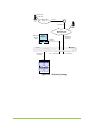
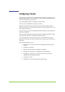
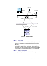
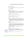
Figure 112. Cluster Topology
STEP 1. ATTACH CABLES
Attach an HSSDC-DB9 fibre channel cable from your JBOD appliance to one of
the storage ports on the back panel of V-Switch 1. See #1 in Figure 112.
Depending on your appliance, you need to plug a terminator into one of the
JBOD ports.
Attach an RJ45 copper 1 Gbit Ethernet cable from the Ethernet port Eth1 on
the front panel of V-Switch 1 to your Telnet terminal. See #2 in Figure 112.
Attach another RJ45 copper 1 Gbit Ethernet cable from the Ethernet port Eth1
on the front panel of the second V-Switch, Vswitch2, to your Telnet terminal.
STEP 2. POWER UP STORAGE DEVICE
Power up the JBOD appliance first to allow both V-Switches to register it in their
network scan.