


66 SANRAD V-Switch User Manual
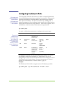
Configuring IP Routing
To enable communications between the V-Switch and IP networks located
outside the V-Switch LAN, you must configure IP routing paths for each
external network port. The IP route begins with a specified network port on
the V-Switch and ends at the external network IP address. Just as each IP
address is unique, each IP routing path is unique. There can be only one IP
route to a given external network IP address per V-Switch.
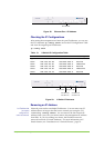
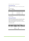
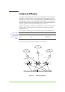
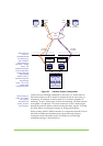
In Figure 31, page 68, you have two V-Switches connected to three different
LANs (A, B, C). In turn, each LAN is connected to at least one external
network (D, E, F).
On V-Switch 1, network ports Eth1 and Eth2 can both access Network D:
PORT LAN ROUTER LEG
ETH1 A 20.20.10.20
You can configure
only one IP route to a
given external
network on your V-
Switch.
ETH2 B 30.30.20.20
Only one of these paths can be configured for V-Switch 1.
Cloud
10227
V Switch 1 V Switch 2
Clou
d
Clou
d
Network D
Network E
R
R
R
10.10.20.0
20.20.10.20
30.30.20.20
12.11.20.20
10.11.30.0
20.22.11.11
10.12.40.0
Etherne
t
LAN A
Etherne
t
LAN C
Etherne
t
LAN B
Network F
D
B
D
A
Figure 31. IP Routing Options