


Sample Configurations 273
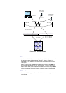
STEP 3. POWER UP V-SWITCHES
Connect the power cord to V-Switch 1 and then to the electric socket. The V-
Switch powers up. The fan assembly is running and the LCD panel displays:
V-Switch 3000
Status: OK
Connect the power cord to V-Switch 2 and then to the electric socket. The V-
Switch powers up. The fan assembly is running and the LCD panel displays:
V-Switch 3000
Status: OK
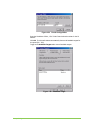
STEP 4. I
NITIALIZE V-SWITCH 1
Use the LCD display and control buttons on V-Switch 1 to configure the V-
Switch management port IP address and mask.
Toggle to the IP Configure ETH1 Port screen.
Press Enter. The IP Configuration screen appears.
IP CONFIG
Press Enter again. The IP Config ETH1 Port screen appears.
IP Config
ETH1 Port
Press Enter. The Insert IP screen appears.
Insert IP
0 0 0.0 0 0.0 0 0.0 0 0
Enter the management port IP address. The left/right buttons toggle
between places in the IP address. The up/down buttons scroll between
numbers. Press Enter after inputting the full address.
Insert IP
2 1 2.1 9 9.0 4 3.0 4 1
Press Enter to enter the IP address and progress to the IP Mask screen.
Mask
2 5 5.2 5 5.2 5 5.0 0 0
If you want to change from the default mask, use the left/right buttons
to toggle between places in the mask and the up/down buttons scroll
between numbers.
Press Enter to enter the IP mask and return to the main V-Switch
Status screen.
V-Switch 3000
Status: OK