


72 SANRAD V-Switch User Manual
Introduction to V-Switch Clusters
Two V-Switches can be concurrently connected to the same FC storage
devices to balance volume exposure thus creating a V-Switch cluster. In a
cluster, each V-Switch interacts in an active-active, peer-to-peer fashion
with the other V-Switch, or neighbor, in the cluster. No one V-Switch must
be configured specially to act as the master V-Switch in the cluster
providing higher flexibility in building a cluster.
All virtual volumes are accessible to each V-Switch and the exposing V-
Switch is defined per volume.
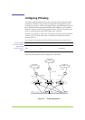
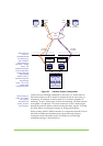
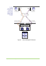
In Figure 32, page 73, two V-Switches are connected to one FC JBOD. From
the four physical disks, two virtual volumes have been created, both equally
accessible to both V-Switches.
SANRAD V-Switches
are both fully
operational in a
cluster. No V-Switch
must sit in stand-by
mode.
Both V-Switches are also connected to two hosts via the IP SAN. The
volume exposure of the two virtual volumes is balanced equally between
the two V-Switches. Volume 1 is exposed via V-Switch 1 to Host 1,
represented by the orange dashed line. Volume 2 is exposed via V-Switch
2 to Host 2, represented by the purple dotted line.
The volume exposure is balanced equally between the two V-Switches
with one volume exposed on each V-Switch for best resource utilization.