


276 SANRAD V-Switch User Manual
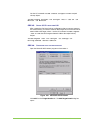
keyboard. The CLI prompt > appears. You are now logged in and
ready to begin configuring your V-Switch for volume virtualization and
exposure.
STEP 9. NAME V-SWITCH 2
Use the CLI command init to name V-Switch 2. You will need this name later
for exposing volumes.
init –n VSwitch2
STEP 10. C
REATE CLUSTER
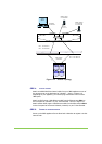
You need to enable your two V-Switches to act as one unit to provide V-Switch
failover. To do this, you need to tell each one that the other one exists. Use
the CLI command
neighbor add to tell each V-Switch that it has a
neighbor.
To V-Switch 1, add V-Switch 2 as a neighbor.
neighbor add –nb VSwitch2 –ip 212.199.43.42
To V-Switch 2, add V-Switch 1 as a neighbor.
neighbor add –nb VSwitch1 –ip 212.199.43.41
STEP 11. C
ONFIGURE V-SWITCH 1 NETWORK PORT ETH 1 IP ADDRESSES
Use the CLI command ip config set to configure the network port Eth 1
for communications between VSwitch1 and the host stations on VSwitch1. Set
the IP address as active (1) to allow read/write commands to pass through this
IP address.
ip config set –if eth1 -ip 212.199.43.56 –im
255.255.255.0 –act 1
Now, use the CLI command ip config set to configure the IP takeover
address for Eth 1. This IP address will be the IP address of Eth 1 on VSwitch2.
The address will sit inactive (2) unless VSwitch2 goes offline. Then VSwitch1
will activate (1) this address and direct all read/write commands to this address
through Eth1 on VSwitch1.
ip config set –if eth1 -ip 212.199.43.75 –im
255.255.255.0 –act 2
STEP 12. C
ONFIGURE V-SWITCH 1 ISCSI PORTALS
The port number you
set in the CLI must
coincide with the port
number you set in
your iSCSI initiator
configuration.
Use the CLI command iscsi portal create to configure the iSCSI
portal on network port Eth 2 for iSCSI communications between VSwitch1 and
the host stations.
iscsi portal create –ip 212.199.43.56 –p 5003