


Sample Configurations 263
Configuring the V-Switch with a Single IP
Routing Path
You have just purchased a V-Switch to manage your company’s storage
network. A section of your company’s employees is located in your local
branch offices and a section is stationed in your overseas offices.
You need to configure volume access for both the local and overseas
employees.
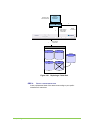
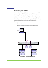
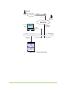
In this example, the storage network consists of:
One JBOD appliance with four disks of equal capacity (the actual
capacity is not important) connected to the V-Switch.
One computer terminal with a network card (NIC) acting as the
management station for the V-Switch connected to the Ethernet
port Eth1 via a 1 Gbit Ethernet RJ45 cable. See #2 in Figure 106,
page 264.
One LAN connection to Ethernet port Eth2 via a 1 Gbit Ethernet
RJ45 cable. See #3 in Figure 106, page 264.
One external network connection to the LAN.
The hosts 1 and 2 run on the Windows™ 2000 platform and have the IBM
iSCSI initiator v.1.2.2 software installed.
An IP address has already been assigned to the management station.
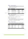
The management port Eth 1 IP address will be assigned 100.100.100.2.
The network port Eth 2 IP address will be assigned 212.199.43.56.
The iSCSI portal for network port Eth2 will be set to 5003.
Your network should mimic Figure 106, page 264.
This example explains how to:
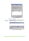
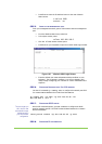
Initialize your V-Switch via the LCD display panel and control
buttons.
Manage your V-Switch through a direct 1 Gbit Ethernet connection
to the V-Switch Eth 1 network port.
Configure IP routing to a remote IP network.
Configure network port Eth 2 for volume exposure to hosts.
Create a RAID 10 volume.
Expose a RAID 10 volume to both local and remote hosts.