


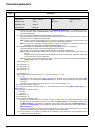

Status parameters
80
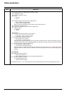
Possible values in CiA402 profile
bit 0: "Ready to switch on", awaiting power section line supply
bit 1: "Switched on", ready
bit 2: "Operation enabled", running
bit 3: "Fault"
= 0: No fault
= 1: Fault
bit 4: "Voltage enabled", power section line supply present
= 0: Power section line supply absent
= 1: Power section line supply present
When the drive is powered by the power section only, this bit is always at 1.
bit 5: "Quick stop"/Emergency stop
bit 6: "Switched on disabled", power section line supply locked
bit 7: "Warning", alarm
= 0: No alarm
= 1: Alarm
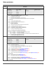
bit 8: Reserved
bit 9: "Remote", command or reference via the network
= 0: Command or reference via the terminals
= 1: Command or reference via the network
bit 10: "Target reached", reference reached
= 0: The reference is not reached
= 1: The reference has been reached
When the drive is in speed mode, this is the speed reference. When the torque function is activated, refer to the
description of this function (see the Programming Manual). When the drive stops, the reference has been reached.
bit 11: "Internal limit active", reference outside limits
= 0: The reference is within the limits
= 1: The reference is not within the limits
When the drive is in speed mode, the limits are defined by the "Low speed (LSP)" and "High speed (HSP)"
parameters. When the torque function is activated, refer to the description of this function (see the Programming
Manual).
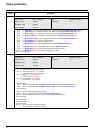
bit 12: Reserved
bit 13: Reserved
bit 14: "Stop key", STOP via stop key
= 0: STOP key not pressed
= 1: Stop triggered by the STOP key on the graphic display terminal
bit 15:"Direction", direction of rotation
= 0: Forward rotation at output
= 1: Reverse rotation at output
The combination of bits 0, 1, 2, 4, 5 and 6 defines the state in the DSP 402 state chart (see the CiA402 profile section).
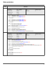
Code Description