


Status parameters
84
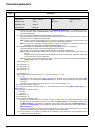
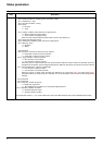
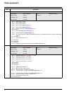
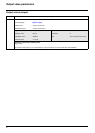
LRS6 Parameter name: Extended status word 6
Logic address: 3255 = 16#0CB7 Type: WORD (bit register)
CANopen index: 2002/38 Read/write: R
INTERBUS index: 5FB9/23
DeviceNet path: 71/01/38
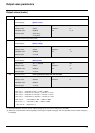
bit 0: = 1: Alarm group 1 is active
bit 1: = 1: Alarm group 2 is active
bit 2: = 1: Alarm group 3 is active
bit 3: = 1: Probe 1 alarm: [PTC1 alarm] (PtC1)
bit 4: = 1: Probe 2 alarm: [PTC2 alarm] (PtC2)
bit 5: = 1: LI6 PTC probe alarm: [LI6=PTC alarm] (PtC3)
bit 6: Reserved
bit 7: = 1: External fault [External fault alarm] (EtF)
bit 8: = 1: Undervoltage alarm [Undervoltage] (USA)
bit 9: = 1: The power section line supply loss detection threshold for a controlled stop has been reached (undervoltage
warning)
bit 10: Reserved
bit 11: = 1: Drive overheat alarm (tHA)
bit 12: Reserved
bit 13: Reserved
bit 14: Reserved
bit 15: = 1: Current or torque limit alarm after time-out [Trq/I limit. time out] (StO)
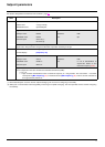
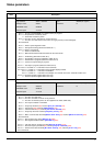
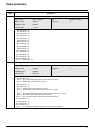
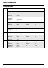
LRS7 Parameter name: Extended status word 7
Logic address: 3256 = 16#0CB8 Type: WORD (bit register)
CANopen index: 2002/39 Read/write: R
INTERBUS index: 5FB9/24
DeviceNet path: 71/01/39
bit 0: = 1: Reference channel 1 (Fr1) or 1B (Fr1b) is active
bit 1: = 1: Reference channel 2 (Fr2) is active
bit 2: = 1: Command channel 1 (Cd1) is active
bit 3: = 1: Command channel 2 (Cd2) is active
bit 4: = 1: Reference channel 1B (Fr1b) is active
bit 5: Reserved
bit 6: Reserved
bit 7: Reserved
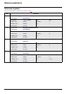
bit 8: = 1: IGBT thermal state alarm
bit 9: = 1: Braking resistor overload alarm
bit 10: = 1: Alarm sent by the "Controller Inside" card
bit 11: = 1: 4-20 mA alarm on analog input AI3: [AI3 4-20mA loss] (LFF3)
bit 12: = 1: 4-20 mA alarm on analog input AI4: [AI4 4-20mA loss] (LFF4)
bit 13: = 1: DC bus precharging contactor controlled (DC0)
bit 14: = 1: Flow limitation function active
bit 15: Reserved (= 0)
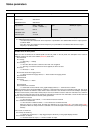
Code Description