


4-12
Sun Fire V20z and Sun Fire V40z Servers—User Guide • March 2005
4.5 Customer-Replaceable-Unit
Replacement Procedures
Caution –
Before touching or replacing any component inside the server, disconnect
all external cables. If possible, place the server on a grounded electrostatic-discharge
(ESD) pad and ALWAYS wear a properly grounded, antistatic wrist strap.
Caution –
The auxiliary CPU card is not a hot-swappable component. You must
power down the server before removing the card.
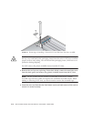
Note –
It is not necessary to remove the system cover when working with the CPU
card. Procedures involving the CPU card can be performed with the server mounted
in a rack. If it is in a rack, pull the server forward from the rack about 3 inches
(76 mm) to provide clearance before opening the CPU card door.
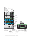
The following components are customer-replaceable units (CRUs):
■
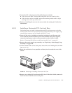
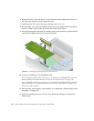
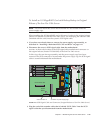
PCI Card(s) and PCI riser (see “PCI Card” on page 4-13)
■
Hard Disk Drives and Carriers (see “SCSI Hard Disk Drive and Carrier” on
page 4-21)
■
DVD/Diskette Drive Assembly (see “DVD-ROM/Diskette Drive Assembly” on
page 4-24)
■
CPU Card (optional) (see “CPU Card” on page 4-25)
■ Operator panel and LCD assembly (see “Operator Panel and LCD Assembly” on
page 4-29)
■ SCSI Backplane Assembly (see “SCSI Backplane Assembly” on page 4-30)
■ Cooling Fans (see “Replacing an Individual Cooling Fan” on page 4-32)
■ Front fan-cage assembly (see “Replacing the Front Fan-Cage Assembly” on
page 4-34)
■ Rear fan-cage assembly (see “Replacing the Rear Fan-Cage Assembly” on
page 4-35)
■ Power Supplies (see “Replacing an Individual Power Supply” on page 4-37)
■ Power-Supply Cage Assembly (see “Replacing a Power-Supply Cage Assembly”
on page 4-39)
■ Memory VRMs (on motherboard and CPU card) (see “Memory Voltage-Regulator
Modules” on page 4-41)