4-78 Sun Fire V20z and Sun Fire V40z Servers—User Guide • March 2005
4.6 Sun Fire V40z Indicators, Switches and
Jumpers
4.6.1 Sun Fire V40z Motherboard and CPU Card
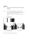
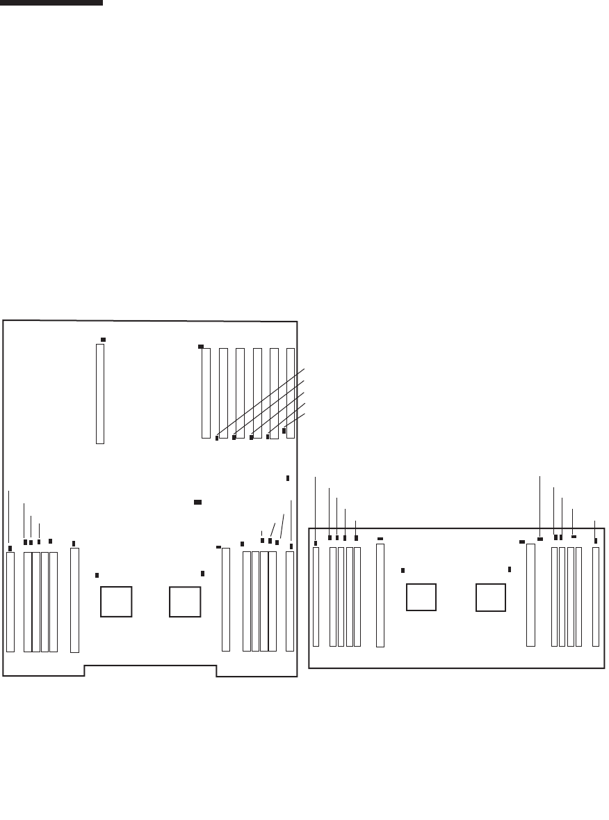
FIGURE 4-41 shows the locations of the activity indicator LEDs and the Clear-CMOS
jumper on the motherboard and the optional CPU card.
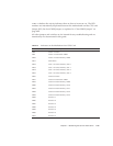
TABLE 4-3 defines the
component to which each fault indicator LED corresponds.
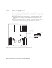
Jumper J125, the clear-CMOS jumper, is explained in “Clear-CMOS Jumper” on
page 4-80.
FIGURE 4-41 Sun Fire V40z Motherboard, Showing LED Locations
Server/motherboard front
Server/motherboard rear
CPU card rear
CPU card front
CPU0 CPU1
CPU2 CPU3
LD25
LD26
J125
LD18
LD23
LD22
LD21
LD20
LD17
LD16
LD8
LD9
LD11
LD12
LD10
LD15
LD14
LD13
LD27
LD28
LD29
LD30
LD31
LD17
LD16
LD8
LD18
LD23
LD22
LD21
LD20
LD12
LD13
LD14
LD15
LD10
LD9


