Chapter 3 Maintaining the Sun Fire V20z Server 3-45
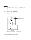
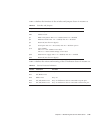
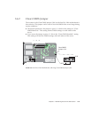
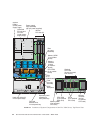
TABLE 3-3 defines the functions of the switches and jumpers shown in FIGURE 3-35.
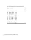
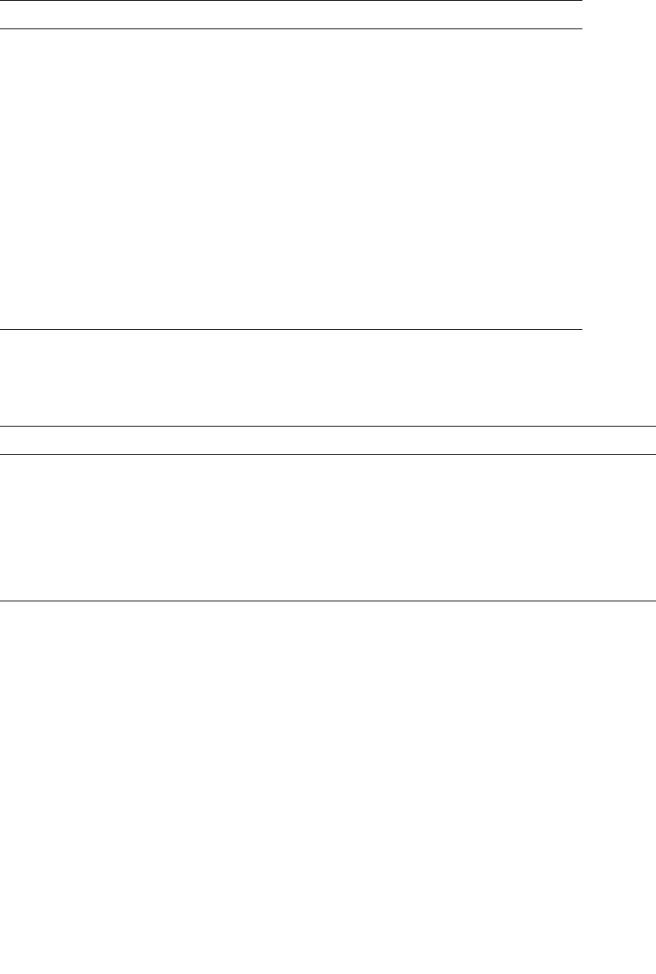
TABLE 3-4 defines the actions and meaning of the SP indicators shown in FIGURE 3-35.
TABLE 3-3 Switches and Jumpers
Component Function or Definition
SW3 Alternate power on
SW7 Platform reset
J11 BIOS write-protect: Pins 1+2 = enabled, Pins 2+3 = disabled
J12 BIOS Boot block: Pins 1+2 = enabled, Pins 2+3 = disabled
J13 Reserved (not shown in figure)
J19 Serial port: Pins 1+2 = SP console, Pins 2+3 = Platform port A
J110 Clear CMOS:
Pins 1+2 = clear CMOS on next boot,
Pins 2+3 = retain CMOS settings on next boot
J108 NPUI Power supply: Pins 1+2 = disabled, Pins 2+3 = enabled
J105 Reserved (not shown in figure)
TABLE 3-4 Service Processor Indicators
Indicator Initialization Run State
D46 Off, Off, Blinks twice Stays on
D47 Off, Blinks twice
D48 Blinks twice Stays on
D56 Off, Off, Blinks twice Stays on if Ethernet cable is connected to top SP port.
D57 Off, Off, Blinks twice Stays on if Ethernet cable is connected to bottom SP port


