4-72 Sun Fire V20z and Sun Fire V40z Servers—User Guide • March 2005
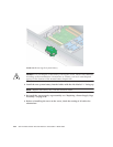
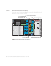
6. Remove the screws that secure the operator-panel assembly in place: there are two
screws on top and one captive screw inside the chassis, just behind the assembly
(see
FIGURE 4-19).
7. Slide the operator-panel assembly through the front panel of the server.
8. Disconnect the operator-panel cable and the USB cable from the assembly.
9. Remove the cables from the chassis.
10. Feed the new cables through the opening in the front panel, with the ends of each
cable labelled "Motherboard" toward the rear of the chassis.
11. Connect the new operator-panel cable and the USB cable to the assembly.
12. Slide the assembly into the opening, while pulling the cables back into the
chassis.
13. Push the assembly in until the top screw holes line up.
14. With the three screws, re-attach the assembly to the chassis.
15. Re-seat the service loop for the flat cables into the plastic retainer clip on the
chassis wall.
16. Re-seat the USB cable in its plastic retainer clips on the wall.
If you have no other cables to replace, jump to “Repositioning the Cables” on
page 4-72. Otherwise, continue in the procedure with your next type of cable.
Repositioning the Cables
This section is for the the operator-panel board cable, the internal USB cable and the
DVD-ROM/Diskette drive assembly cable.
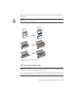
Caution – Ensure that you do not damage the memory voltage-regulator
module (VRM) when you are re-installing the PCI bracket guide.
1. Lay the cables flat against the chassis wall, outside of the memory VRM on that
side.
2. Connect the new cables to the motherboard.


