


Installation 2 - 29
The switch must be rated at 5V, 10 mA and it should have a operating temperature, sealing and life cycle
applicable for the environment that it is used in.
The mechanical switch must be a Normally Open type of switch.
The supply voltage for the solid state switch is 5 VDC (500 mA max.). When the switch is depressed the OUT
pin is pulled low.
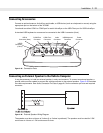
The switch must be mounted permanently and must be positioned in such a way so that the switch is
depressed when the accelerator pedal is not pressed (vehicle at rest). When the accelerator pedal is pressed,
the switch should open and stay open until the pedal is released completely.
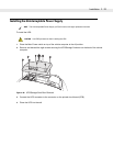
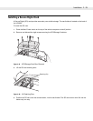
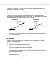
Figure 2-37
Switch Installation Example
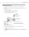
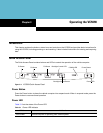
Cable Installation
One end of the cable connects to a customer provided switch and the other end connects to the COM1 or
COM2 port on the vehicle computer.
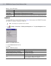
To install the Vehicle In-Motion Detector cable:
1. Follow these recommendations when installing the cable:
•
Establish a neat route for the cable, staying clear of moving parts or hot surfaces.
•
Place the cable in a rigid sleeve or conduit to protect the cable.
•
When the cabling must go through a panel, use a suitable gland.
•
When fixing the conduit or cable on the outside of a vehicle, use P-Clips. Either drill and tap the hole or
use a nut and bolt to secure the clip.
•
Ensure the cable does not have tight bends. The minimum recommended radius is 2.5".
•
Solder all wire connections.
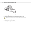
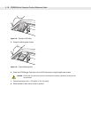
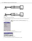
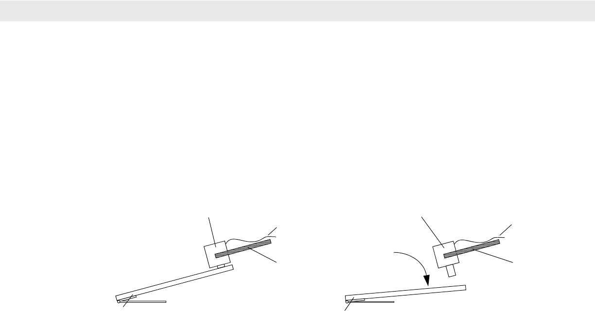
2. Wire the cable and switch as shown in Figure 2-38.
Switch (Closed)
Accelerator
Pedal
Switch (Open)
Accelerator
Pedal
Mounting
Hardware
Mounting
Hardware
Cable
Cable
Vehicle Stationary
Vehicle In-Motion
Note: Diagram is for concept only. Actual switch, pedal, mounting hardware and installation vary depending upon the
type of vehicle and hardware used.