Chapter 1 Overview of the TimeProvider
Overview
22 TimeProvider User’s Guide 097-58001-02 Revision G – April 2008
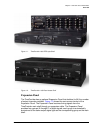
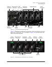
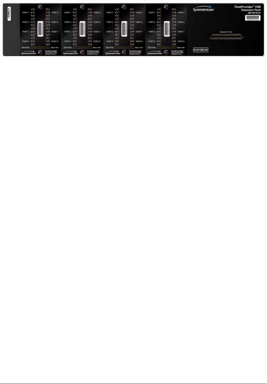
Figure 1-3. TimeProvider 1100 Expansion Panel
Inputs
The TimeProvider accepts the following types of input signals:
Primary Reference Signals (PRS): 1.544 MHz, 2.048 MHz, 5 MHz, 6.312 MHz, or
10 MHz
Span input signals:
– E1 or 2.048 MHz analog; user-selectable CAS or CCS framing
– T1 D4, Extended Superframe (ESF)
– 1.544 and 6.312 MHz
– Composite Clock, including Japan Composite Clock (JCC) and Japan
Composite Clock with 400 Hz (JCC4) signals
GPS input:
– GPS signal from the stand-alone TimeProvider Interface Unit (TPIU)
– GPS signal into the TPIU integrated with the IMC (IMC/TPIU card)
The TimeProvider qualifies the input reference signals and detects the following
errors: Loss of Signal (LOS), Alarm Indication Signal (AIS), Loss of Framing, and
Synchronization Status Messages (SSM) where applicable. Reference Input
Signals, on page 34, describes the inputs in more detail.
Outputs
The TimeProvider produces a variety of outputs to meet different signal standards.
Output signal types include 8 kHz, 1.544 MHz, 2.048 MHz, 6.312 MHz, E1, T1, CC,
JCC, JCC4, and TIA/EIA-B-422 (1.544 and 2.048 MHz). The E1 and T1 signals can
be provisioned with standard framing that meets G.703 formats. The SSM bit
location is user-selectable on E1 outputs; CRC4 must be enabled in order to provide
output SSMs. These outputs are available through one of several different
connector panels. See Output Signals, on page 39, for more information on output
signals.


