


Performance Tests
4–60
TDS 684A, TDS 744A, & TDS 784A Service Manual
H Press the main-menu button Source.
H Press the side-menu button Ch3.
H Set vertical SCALE to 100 mV.
H Press SET LEVEL TO 50%.
H Press MEASURE; then press the main-menu button Select
Measrmnt for Ch2.
H Repeatedly press the side-menu button –more– until Pk-Pk appears
in the side menu (its icon is shown at the left). Press the side-menu
button Pk-Pk.
H Press CLEAR MENU.
b. Check against limits:
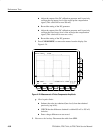
H CHECK that the readout Ch2 Pk-Pk is between 80 mV and 120 mV,
inclusive, for the TDS 684A or is between 88 mV and 132 mV,
inclusive, for the TDS 7XXA.
H Enter voltage on test record.
H Press VERTICAL MENU; then press the side-menu button W to
toggle to the 50 W setting.
H Press CLEAR MENU.
H CHECK that the readout Ch2 Pk-Pk is between 40 mV and 60 mV,
inclusive, for the TDS 684A or is between 44 mV and 66 mV,
inclusive, for the TDS 7XXA.
H Enter voltage on test record.
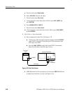
4. Disconnect the hookup: Disconnect the cables from the channel inputs and
the rear panel outputs.
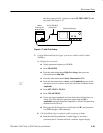
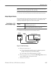
Equipment
Required
One female BNC to clip adapter (Item 3)
Two dual-banana connectors (Item 6)
One BNC T connector (Item 7)
Two 50 W precision cables (Item 5)
One DC calibration generator (Item 9)
Prerequisites See page 4–15. Also, the Digitizing Oscilloscope must have passed
Check Accuracy For Long-Term Sample Rate, Delay Time, and Delta
Time Measurements on page 4–42.
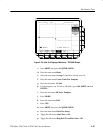
Check Probe
Compensator Output