


Troubleshooting
TDS 684A, TDS 744A, & TDS 784A Service Manual
6–67
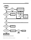
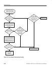
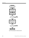
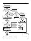
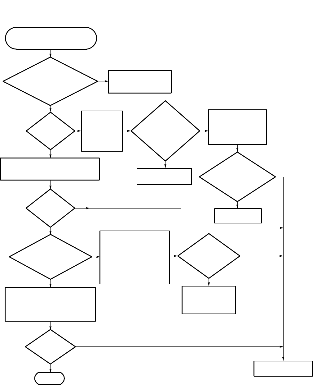
This procedure helps you determine if
the A11 DRAM Processor/Display or
the A12 Front Panel module is bad.
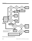
Perform the Low Voltage
Power Supply
troubleshooting
procedure.
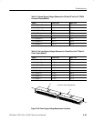
Probe J26 and J27 but DO NOT
REMOVE the cables from the
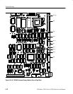
connector (see Figure 6–36).
The voltages will change if the
A11 DRAM Processor/Display
module is not connected to the
power supply. Probe J26 pins 7,
11, 17, and 35, and J27 pin 17.
Yes
No
Done.
Yes
No
No
Yes
Power off and remove the
cable from J2 on the A11
DRAM Processor/Display
module. Probe P2 pins 10
and 8 with an ohm meter.
the cable
from the A11 DRAM
Processor/Display module to the
A12 Front Panel module
securely connected?
Connect the cable and then
perform the Primary
troubleshooting procedure.
Is the
ON/STBY
button working
correctly?
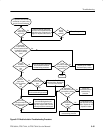
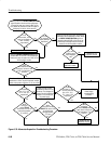
Power off the oscilloscope, remove the cable
from J2 of the A11 DRAM Processor/Display
module (see Figure 6–36), and power back on.
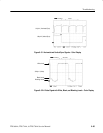
Is
there a
3.125 MHz clock
on J2 pin 25?
Probe J2
pin 2, 6, 7, 11, 16.
Are these pins –15 V, +15 V,
+5 V, –5 .1 V, and +5.1 V
respectively?
No
Yes
Are
these pins
–15 V, +15 V, –5.1 V,
+5 V, and +5.1 V
respectively?
No
Yes
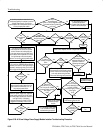
On the A11 DRAM
Processor/Display
module probe J26
pins 3 and 5 with
an ohm meter
(see Figure 6–36).
Does
the resistance
between these two
pins dramatically
decrease when the
ON/STBY button
is toggled?
No
Yes
Replace the Low Voltage
Power Supply.
There must be a problem with the
communication link between the A11
DRAM Processor/Display and the A12
Front Panel. The A12 Front Panel module
has most likely failed. Replace this module.
Does
the Front Panel
work correctly
now?
No
Yes
Replace the A12
Front Panel module.
Replace the A11 DRAM
Processor/Display module.
Does
the resistance
between these two pins
dramatically decrease when the
ON/STBY button is
toggled?
No
Yes
Is
Figure 6–34: Processor/Front Panel Troubleshooting Procedure