


Removal and Installation Procedures
6–26
TDS 684A, TDS 744A, & TDS 784A Service Manual
2. Orient the oscilloscope: Set the oscilloscope so its bottom is down on the
work surface and its front is facing you.
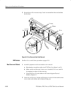
3. Remove the display-frame assembly:
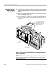
a. Do the procedure Front Cover, Trim Ring, Menu Buttons, and Attenuator
Panel (page 6–22) to remove the front cover and trim ring.
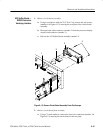
b. Lift the front-panel assembly out of the front subpanel until you can
reach J2 on the front-panel assembly. Disconnect the flex cable coming
from the display-frame assembly at J39 of the front-panel assembly.
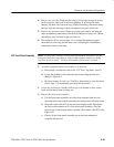
c. Do the procedure Floppy Disk (page 6–42) to remove the floppy disk
drive.
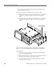
d. Remove the three screws securing the display-frame assembly to the
front subpanel and remove that assembly.
4. Reinstallation:
a. Do, in reverse order, substeps 3b–3d, reversing each step to reinstall the
display-frame assembly. Then see the procedure Front Cover, Trim Ring,
Menu Buttons, and Attenuator Panel (page 6–22) to complete reassemb-
ly of the oscilloscope.
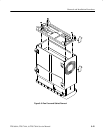
1. Assemble equipment and locate modules to be removed: Have handy a pair
of needle-nose pliers (Item 6). Locate the modules to be removed in the
locator diagram External Modules (see Figure 6–1).
2. Orient the oscilloscope: Set the oscilloscope so the left side is down on the
work surface and its handle is facing upwards.
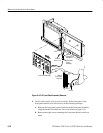
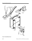
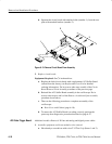
3. Remove the handle:
a. Insert the tips of a pair of needle-nose pliers (Item 6) into the hole of
either handle cap. Push and hold to depress the handle release.
b. While holding the handle released, pull it out of the slot in the handle
cap. Repeat procedure to remove the handle from the other handle cap.
c. Reverse procedure to reinstall.
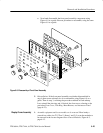
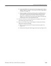
4. Remove the handle caps:
a. Insert the retaining ring pliers (Item 8) into the opening created in the
handle cap when you removed the handle.
b. While using the pliers to expand the handle cap outward, grasp it and
snap it off.
Cabinet Modules