


Removal and Installation Procedures
6–30
TDS 684A, TDS 744A, & TDS 784A Service Manual
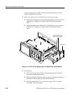
processor/display board; J100 is on the acquisition board.) Reverse these
removal instructions to reinstall.
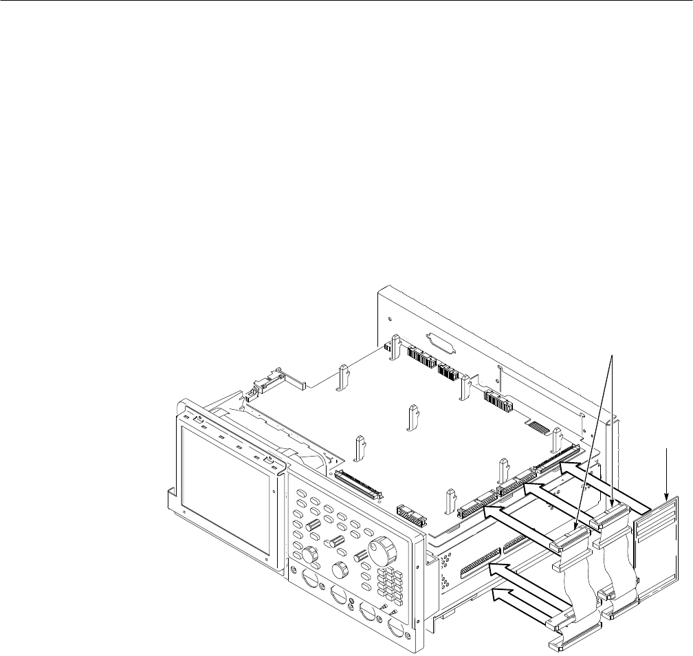
4. Remove the analog-power and digital-power interconnect cables:
a. Unplug the analog-power cable at J26 on the display processor board, at
J5 on the low-voltage power supply, and at J700 on the acquisition
board.
b. Unplug the digital-power cable at J27 on the display processor board, at
J6 on the low-voltage power supply, and at J101 on the acquisition
board.
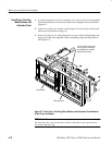
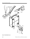
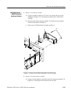
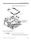
Analog and Digital Power
Cables (Interchangeable)
A14 D1 Bus
Figure 6–11: A14 D1 Bus and Analog-Power and Digital-Power Cables Removal
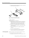
5. Reinstallation:
a. Do in reverse order steps 3 and 4, reversing the procedure outlined in
each step to reinstall the assembly.
b. When installing the D1 bus be sure to orient it so the single connector at
the bottom of the bus plugs into the acquisition board.
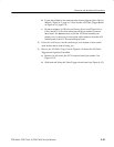
c. See the procedure Rear Cover and Cabinet (page 6–18) to complete
reassembly of the oscilloscope.