


Adjustment Procedures
5–18
TDS 684A, TDS 744A, & TDS 784A Service Manual
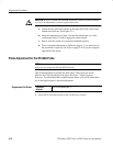
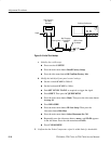
H Press SHIFT; then press ACQUIRE MENU.
H Press the main-menu button Mode. Then press the side-menu button
Average 16.
H Push SET LEVEL TO 50% as required to trigger the signal.
H Advance the horizontal SCALE to 5 ns.
H Press HORIZONTAL MENU.
H Press the main-menu button Trigger Position; press the side-menu
button Set to 20%.
H Press SAVE WAVEFORM.
H Press the main-menu button Save Waveform. Then press the
side-menu button To Ref 1.
H Press MORE. Then push the main-menu button Ref 1.
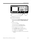
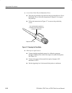
b. Display the test signal:
H Disconnect the tunnel diode pulser at CH 1 and remove the 10X
attenuator.
H Connect the output of the tunnel diode pulser through a BNC-fe-
male-to-BNC-female adapter to a BNC-to-probe tip adapter.
H Install the probe on CH 1.
H Plug the probe tip from the probe into the BNC-to-probe tip adapter.
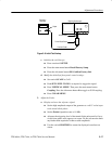
H Press VERTI+CAL MENU; then press CH 1.
H Press the main-menu button Coupling. Then press the side-menu
button W to toggle to 1 MW coupling.
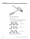
H Push SET LEVEL TO 50% as required to trigger the signal.
H Adjust the triggering level of the tunnel diode pulser until a five to
six division square wave appears on screen. Do not advance the knob
any further than required to achieve stable amplitude.
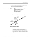
c. Make the adjustments:
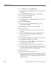
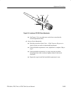
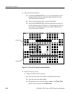
H Locate the various adjustments in Figure 5–9.
H Manually adjust the front-corner response of the probe to best match
the response of the Ref 1 waveform. It is more important to match
the response during the first 5 ns than during the entire first 20 ns the
adjustments affect.