


Removal and Installation Procedures
TDS 684A, TDS 744A, & TDS 784A Service Manual
6–19
3. Disconnect the line cord: Unplug the line cord from its receptacle at the rear
cover.
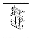
4. Remove rear cover: Remove the four screws securing the rear cover to the
oscilloscope. Lift off the rear cover.
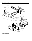
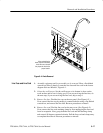
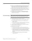
5. Remove the cabinet:
a. At the rear of the cabinet, grasp its left and right edges.
b. Pull upward to slide the cabinet off the oscilloscope. Take care not to
bind or snag the cabinet on the oscilloscope’s internal cabling as you
remove it.
STOP. DO NOT do steps 6 through 8 to remove the EMI gasket(s) unless they
must be replaced due to damage. If you are not replacing those gaskets, skip to
step 9.
When reinstalling EMI gaskets and/or the oscilloscope cabinet, carefully follow
the instructions given. Unless they are performed properly, the oscilloscope may
not meet its emissions requirements (EMI).
6. Assemble equipment and locate modules to be removed:
a. Have handy a pair of needle-nose pliers (Item 6).
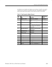
b. Locate the modules to be removed in the locator diagram External
Modules, Figure 6–1.
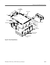
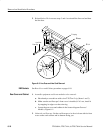
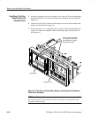
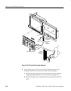
7. Remove the EMI gaskets:
a. Look for the point where the ends of the gasket touch in the channel at
the rear edge of the cabinet.
b. Use a pair of needle-nose pliers to pry up one of the ends.
c. Grasp the EMI gasket, and gently pull it out of the its channel.
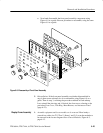
d. Repeat substeps a through c to remove the gasket from its channel on the
front casting.
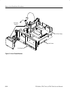
8. Reinstallation of EMI gaskets: Press each EMI gasket back into its groove at
the rear edge of the cabinet or front casting. Make sure the ends of the gasket
touch, but do not overlap, when installing. (Cut off excess length if required
to prevent overlap.)
9. Reinstallation of cabinet and rear cover:
a. Do in reverse order steps 3 and 4 to reinstall the cabinet.