Brief Procedures
TDS 684A, TDS 744A, & TDS 784A Service Manual
4–11
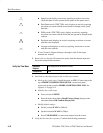
a. One period of the square-wave probe-compensation signal is about five
horizontal divisions on-screen for the 200 ms horizontal scale setting (set
in step 1c).
b. Rotating the horizontal SCALE knob clockwise expands the waveform
on-screen (more horizontal divisions per waveform period), counter-
clockwise rotation contracts it, and returning the horizontal scale to
200 ms returns the period to about five divisions.
c. The horizontal POSITION knob positions the signal left and right
on-screen when rotated.
3. Remove the test hookup: Disconnect the probe from the channel input and
the probe-compensation terminals.
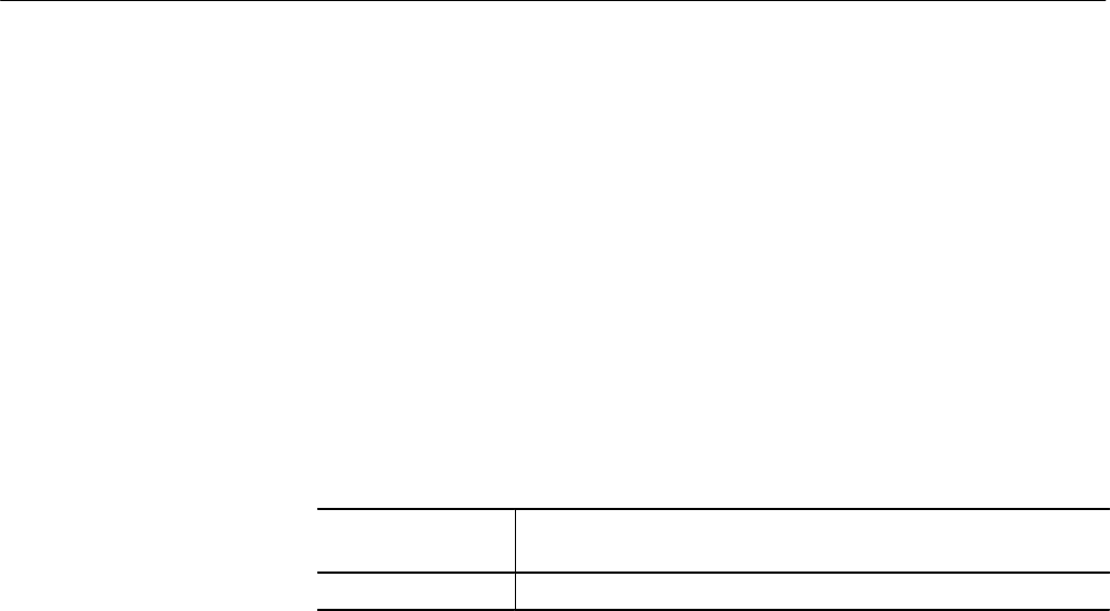
Equipment
Required
One probe such as the P6245 or P6139A
Prerequisites None
1. Install the test hookup and preset the oscilloscope controls:
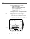
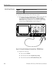
a. Hook up the signal source: Install the probe on CH 1. Connect the probe
tip to PROBE COMPENSATION SIGNAL on the front panel;
connect the probe ground to PROBE COMPENSATION GND. See
Figure 4–3 on page 4–8.
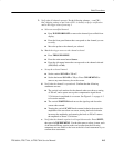
b. Initialize the oscilloscope:
H Press save/recall SETUP.
H Press the main-menu button Recall Factory Setup.
H Press the side-menu button OK Confirm Factory Init.
c. Modify default settings:
H Set the vertical SCALE to 200 mV.
H Set the horizontal SCALE for the M (main) time base to 200 ms.
H Press TRIGGER MENU.
H Press the main-menu button Mode & Holdoff.
H Press the side-menu button Normal.
H Press CLEAR MENU to remove the menus from the screen.
Verify the Main and
Delayed Trigger Systems


