


Adjustment Procedures
5–16
TDS 684A, TDS 744A, & TDS 784A Service Manual
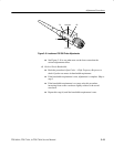
a. Access Inner Probe Tip and Adjustment Ports:
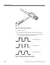
H The probe tip should be exposed from the procedure Measure Probe
Bandwidth. If not, follow the instructions in Figure 5–5 to expose
the probe tip.
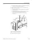
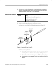
H Follow the instructions in Figure 5–7 to remove the probe body
covers.
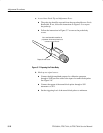
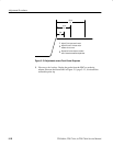
Use a small standard screwdriver to
pry between the cover and metal cord
connector to pop off cover.
Repeat for lower cover.
Figure 5–7: Exposing the Probe Body
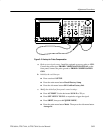
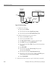
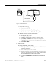
b. Hook up test-signal source:
H Connect the high-amplitude output of a calibration generator,
through a 50 W precision cable to the input of a tunnel diode pulser.
See Figure 5–8.
H Connect the output of the tunnel diode pulser through a 10X
attenuator to CH 1.
H Set the triggering level of the tunnel diode pulser to minimum.