


Troubleshooting
6–64
TDS 684A, TDS 744A, & TDS 784A Service Manual
No
Yes
Replace the A11 DRAM
Processor/Display module.
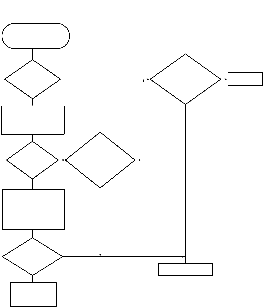
Is
the display
legible but the horizontal
and/or vertical sync do
not look
ok?
Do
J18 pins 1 and 2
on the A11 DRAM
Processor/Display module
(see Figure 6–38) have
signals similar to
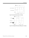
Figure 6–31?
No
Yes
Replace the A30
Display Assembly.
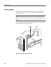
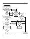
Power the oscilloscope off and
disconnect the cable from J5 on the
A11 DRAM Processor/Display
module (see Figure 6–38) then
power back on.
Are
J5 pins 1 and 2 at
+25 V and J5 pins 3
and 4 at +5.1 V?
No
Yes
On the A11 DRAM
Processor/Display module probe
J27, but DO NOT REMOVE the
cable from the connector. The
voltages will change if the A11
DRAM Processor/Display is not
connected to the power supply.
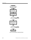
Perform the Low Voltage
Power Supply
troubleshooting
procedure.
Does
J62 pin 1
on the A11 DRAM
Processor/Display module
(see Figure 6–38) have a
video signal with the
same levels as
Figure 6–32?
No
Yes
No
Yes
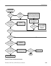
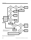
This procedure helps you
determine whether the color
display or the A11 DRAM
Processor/Display module is bad.
Are J27
pin 1 at +25 V and J27
pin 17 at +5.1 V? (See
Figure 6–36.)
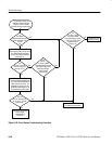
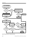
Figure 6–30: Color Display Troubleshooting Procedure