


Removal and Installation Procedures
TDS 684A, TDS 744A, & TDS 784A Service Manual
6–49
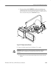
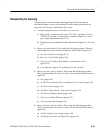
e. Be sure you have read the WARNING on display tube handling and
storage found at the start of this display tube removal procedure. Then
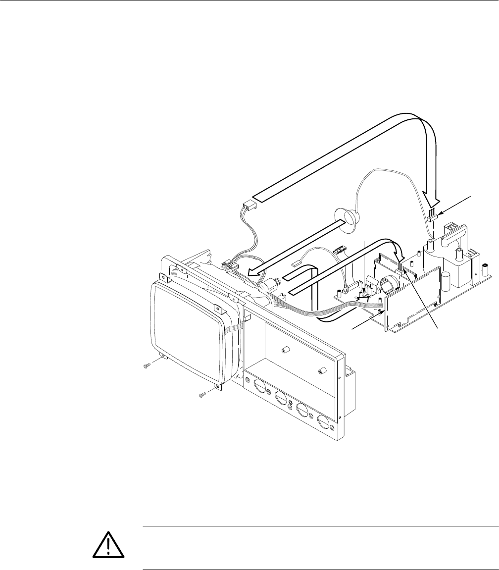
pull the display tube out through the front subpanel to complete removal.
Store as directed in the previous WARNING message.
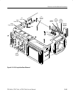
J305
J170
J570
J350
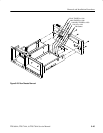
Figure 6–22: Display Assembly Removal
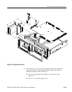
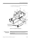
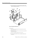
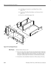
5. Remove the display supply board: Use Figure 6–23 as a guide.
CAUTION. If any RTV Silicon is removed from the oscilloscope, it must be
replaced in order to maintain the warranted characteristics for random
vibration.
a. Remove the six screws that mount the display-driver board to the main
chassis.