Removal and Installation Procedures
TDS 684A, TDS 744A, & TDS 784A Service Manual
6–47
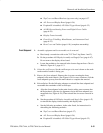
H A14 D1 Bus and Analog-Power and Digital-Power Cables (page 6–29)
H Rear Cover and Cabinet (page 6–18)
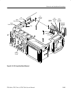
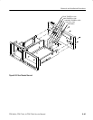
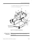
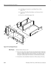
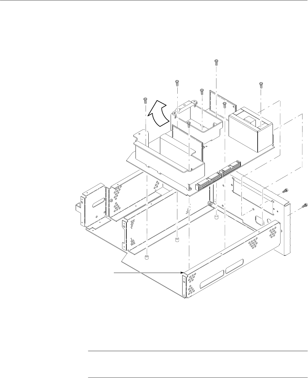
Rotate the edge of the board
upward as indicated to clear
the lip of the main chassis
when lifting this board out.
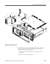
Figure 6–21: A16 Low Voltage Power Supply Removal
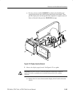
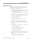
NOTE. The display and the display-driver board are a single module and must be
removed and replaced as such. They are listed as a single module in the
Replaceable Parts List.
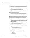
A30 Display Assembly
and Supply Fuse


