


Removal and Installation Procedures
TDS 684A, TDS 744A, & TDS 784A Service Manual
6–17
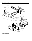
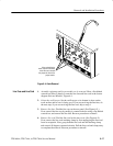
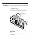
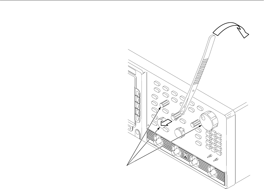
When reinstalling the
knobs, note there are three
sizes. Be sure to reinstall
the proper size knob in the
proper location.
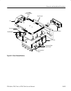
Figure 6–4: Knob Removal
1. Assemble equipment and locate modules to be removed: Have a flat-bladed
screwdriver (Item 5) handy. Locate the line fuse and line cord in the locator
diagram External Modules, Figure 6–1.
2. Orient the oscilloscope: Set the oscilloscope so its bottom is down on the
work surface and its rear is facing you. If you are servicing the line fuse, do
the next step; if you are servicing the line cord, skip to step 4.
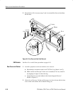
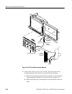
3. Remove line fuse: Find the fuse cap on the rear panel. (See Figure 6–5.)
Now, remove the fuse cap by turning it counterclockwise using a flat-bladed
screwdriver, and remove the line fuse. Reverse procedure to reinstall.
4. Remove line cord: Find the line cord on the rear cover. (See Figure 6–5.)
Now, remove the line-cord retaining clamp by first unplugging the line cord
from its receptacle. Next, grasp both the line cord and the retaining clamp
and rotate it 90 degrees counterclockwise. Pull the line cord and clamp away
to complete the removal. Reverse procedure to reinstall.
Line Fuse and Line Cord