


Removal and Installation Procedures
TDS 684A, TDS 744A, & TDS 784A Service Manual
6–51
H Top Cover and Board Brackets (top cover only) on page 6–37
H A11 Processor/Display Board (page 6–36)
H If option 05 is installed, A29 Video Trigger Board (page 6–32)
H A14 D1 Bus and Analog-Power and Digital-Power Cables
(page 6–29)
H Display-Frame Assembly
H Front Cover, Trim Ring, Menu Buttons, and Attenuator Panel
(page 6–22)
H Rear Cover and Cabinet (page 6–18) (completes reassembly)
1. Assemble equipment and locate modules to be removed:
a. Have handy a screwdriver with a size T-15 TorxR
tip (Items 1 and 2).
b. Do the procedure A30 Display Assembly and Supply Fuse (page 6–47).
Do not remove the display-driver board.
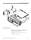
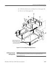
c. Locate the modules to be removed in the locator diagram Inner-Chassis
Modules, Figure 6–2, page 6–13.
2. Orient the oscilloscope: Set the oscilloscope so its rear is down on the work
surface and its bottom is facing you.
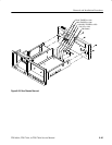
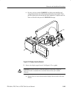
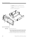
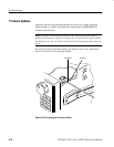
3. Remove the front subpanel: Remove the six screws securing the front
subpanel to the main chassis. (See Figure 6–24 for screw locations.) Lift the
front subpanel up away from the main chassis to complete the removal.
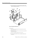
4. Reinstallation: Do the following substeps to reinstall the front subpanel and
reassemble the remainder of the oscilloscope:
a. Align the front subpanel to the main chassis, taking care to ensure that
the main chassis slips into its alignment slot on the front subpanel (see
magnified view, Figure 6–24.) Then reinstall the six screws removed in
step 3.
b. See the procedure A30 Display Assembly and Supply Fuse (page 6–47)
to reinstall the display-frame assembly and display tube.
c. See the following procedures, in the order listed, for instructions for
reinstalling the remaining modules.
H Top Cover and Board Brackets (page 6–37)
H A11 Processor/Display Board (page 6–36)
H If option 05 is installed, A29 Video Trigger Board (page 6–32)
Front Subpanel