


Removal and Installation Procedures
6–18
TDS 684A, TDS 744A, & TDS 784A Service Manual
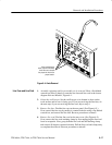
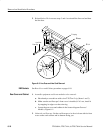
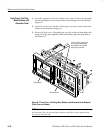
5. Reinstallation: Do in reverse steps 3 and 4 to reinstall the line cord and then
the line fuse.
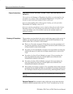
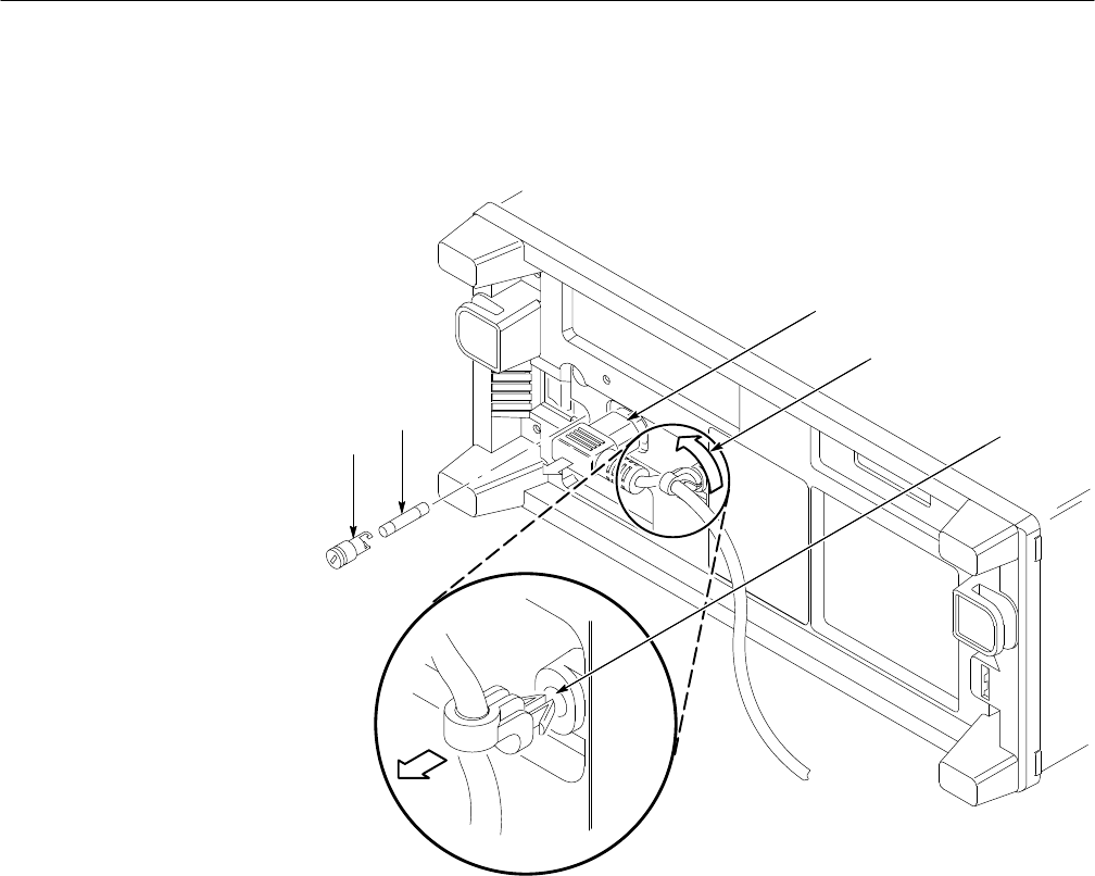
Line Fuse
Fuse Cap
1 Unplug
2 Rotate
3 Pull
Figure 6–5: Line Fuse and Line Cord Removal
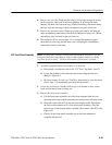
See Rear Cover and Cabinet procedure on page 6–18.
1. Assemble equipment and locate modules to be removed:
a. Have handy a screwdriver with a size T-20 TorxR
tip (Items 1 and 3).
b. Make sure the oscilloscope’s front cover is installed; if it’s not, install it
by snapping its edges over the trim ring.
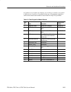
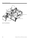
c. Locate the rear cover and cabinet in the locator diagram External
Modules, Figure 6–1.
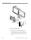
2. Orient the oscilloscope: Set the oscilloscope so its face is down with its front
cover on the work surface and its bottom facing you.
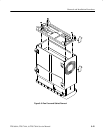
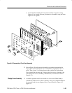
EMI Gaskets
Rear Cover and Cabinet