Brief Procedures
4–10
TDS 684A, TDS 744A, & TDS 784A Service Manual
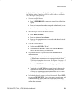
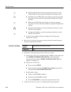
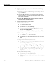
H Sample mode displays an actively acquiring waveform on-screen.
(Note that there is noise present on the peaks of the square wave.)
H Peak Detect mode (TDS 7XXA only) displays an actively acquiring
waveform on-screen with the noise present in Sample mode “peak
detected.”
H Hi Res mode (TDS 7XXA only) displays an actively acquiring
waveform on-screen with the noise that was present in Sample mode
reduced.
H Envelope mode displays an actively acquiring waveform on-screen
with the noise displayed.
H Average mode displays an actively acquiring waveform on-screen
with the noise reduced.
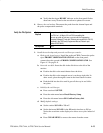
f. Test all channels: Repeat substeps a through e until all four input
channels are verified.
3. Remove the test hookup: Disconnect the probe from the channel input and
the probe-compensation terminals.
Equipment
Required
One probe such as the P6245 or P6139A
Prerequisites None
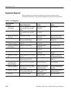
1. Install the test hookup and preset the oscilloscope controls:
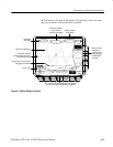
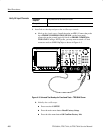
a. Hook up the signal source: Install the probe on CH 1. Connect the probe
tip to PROBE COMPENSATION SIGNAL on the front panel;
connect the probe ground to PROBE COMPENSATION GND. See
Figure 4–3 on page 4–8.
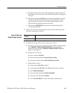
b. Initialize the oscilloscope:
H Press save/recall SETUP.
H Press the main-menu button Recall Factory Setup; then press the
side-menu button OK Confirm Factory Init.
c. Modify default settings:
H Set the vertical SCALE to 200 mV.
H Set the horizontal SCALE to 200 ms.
H Press CLEAR MENU to remove the menus from the screen.
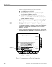
2. Verify that the time base operates: Confirm the following statements.
Verify the Time Base


