


Removal and Installation Procedures
6–50
TDS 684A, TDS 744A, & TDS 784A Service Manual
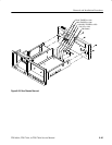
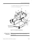
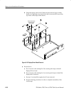
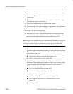
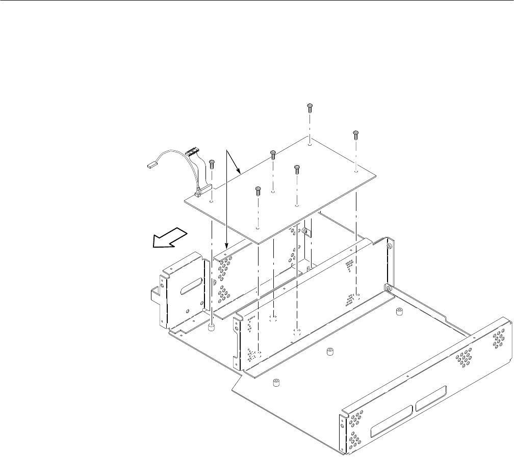
b. Grasp the display driver board. Work from the front and top to tilt the
board so its right edge is up and its left side is down and lift it out of the
top of the oscilloscope’s main chassis.
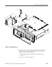
Move circuit board
forward to clear
main chassis.
Figure 6–23: Display Driver Board Removal
6. Reinstallation:
a. Do, in reverse order, substeps 5a–5b, reversing each step to reinstall
Display-Driver board.
b. Do, in reverse order, substeps 4a–4e, reversing each step to reinstall the
display tube if removed.
c. See step 3 to reinstall the supply fuse if it was removed.
d. See the following procedures, in order, to complete reassembly of the
oscilloscope: