


Adjustment Procedures
TDS 684A, TDS 744A, & TDS 784A Service Manual
5–13
3. Disconnect the hookup: Disconnect the probe from the probe compensator
terminals; leave probe installed on CH 1 and leave the oscilloscope control
setup as is for doing the next part of probe adjustment.
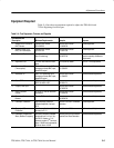
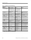
Equipment
Required
One high-frequency sine wave generator with its leveling head
(Item 14)
One BNC-female-to-female BNC adapter (Item 1)
One BNC-to-probe tip adapter (Item 2)
One P6139A 10X probe (Item 17)
1. Install the test hookup and preset the oscilloscope controls:
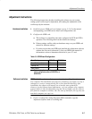
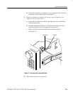
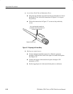
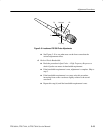
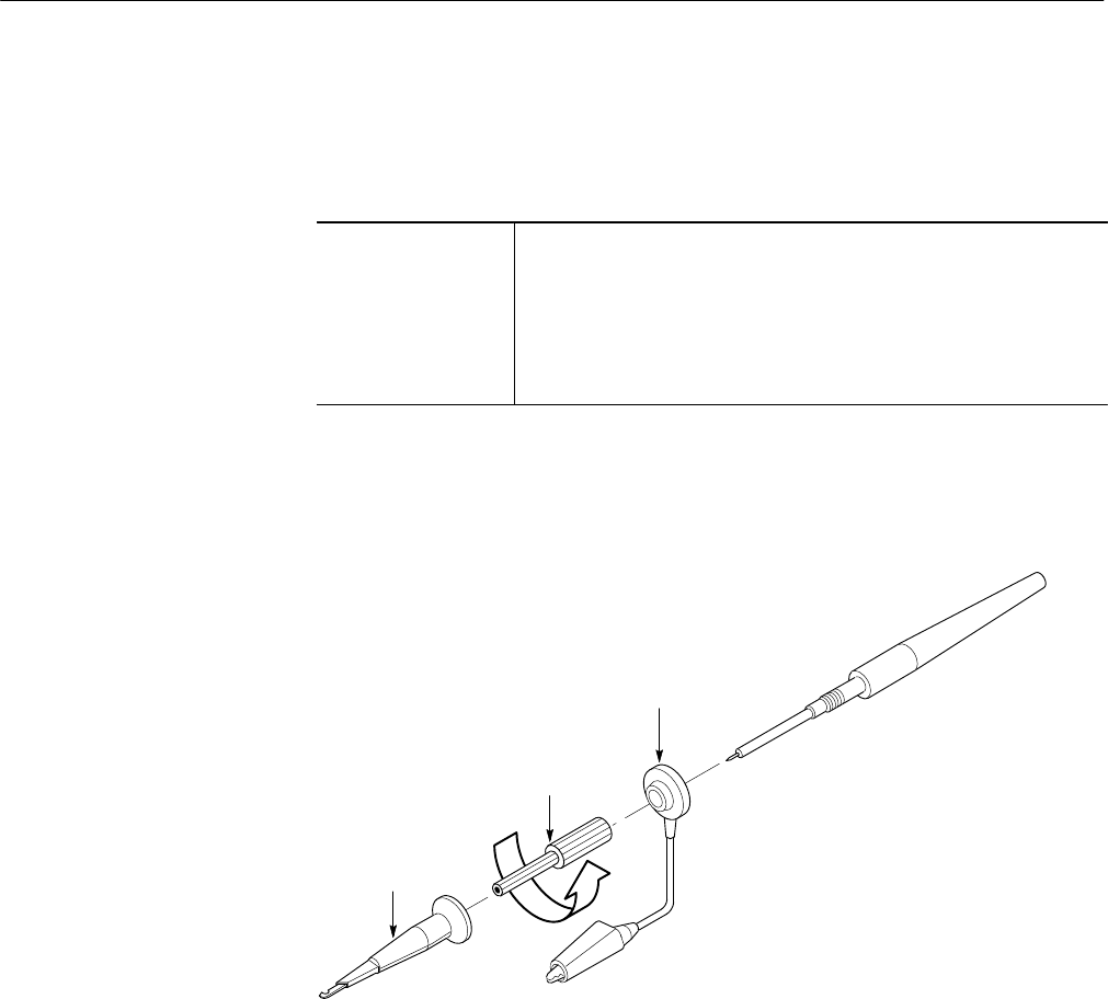
a. Expose the Inner Probe Tip: Follow the instructions in Figure 5–5.
Pull forward to
remove the
retractable hook tip.
1
Unscrew the
ribbed
ferrule tip cover
and pull
forward to remove.
2
Pull forward to
remove the
ground-lead
assembly.
3
Figure 5–5: Exposing the Inner Probe Tip
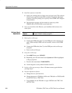
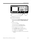
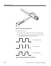
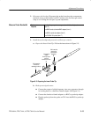
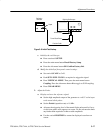
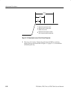
b. Hook up test-signal source:
H Connect the output of a high-frequency sine wave generator, through
its leveling head, to a female-to-female adapter. See Figure 5–6.
H Connect the female-to-female adapter to a BNC-to-probe tip adapter.
H Plug the probe tip from the probe on CH 1 into the BNC-to-probe tip
adapter.
Measure Probe Bandwidth