


Theory of Operation
3–2
TDS 684A, TDS 744A, & TDS 784A Service Manual
selected and the input is overloaded, the processor system switches the input to
the 1 MW position.
Probe Coding Interface. Probe coding interface signals pass through the attenuator
portion of the A10 Attenuator/Acquisition to the acquisition system, where they
are sensed and controlled.
Acquisition System. The acquisition system amplifies the input signals, samples
them, converts them to digital signals, and controls the acquisition process under
direction of the processor system. The acquisition system includes the trigger,
acquisition timing, and acquisition mode generation and control circuitry.
Voltage Controlled Oscillator (VCO). Master clocks for the acquisition system are
generated by the circuitry on the A10 Acquisition board. The circuitry makes up
a phased locked loop. The master clock is divided down by the A10 Acquisition
circuitry under control of the processor system.
D1 Bus. The acquisition system passes the digital values representing the
acquired waveform through the A14 D1 Bus to the A11 DRAM Processor/Dis-
play board. This happens after a waveform acquisition is complete if the digital
signal processor in the processor system requests the waveform.
Processor System. The processor system contains a 68020 microprocessor that
controls the entire instrument. It includes the firmware. It also includes a GPIB
interface. You can reprogram the firmware from a remote controller using the
GPIB and an external software package.
The processor also includes a digital signal processor. This signal processor
processes each waveform as directed by the system processor. Waveforms and
any text to be displayed are passed on to the display system. The A11 DRAM
Processor/Display board contains both the processor and display systems.
Display System. Text and waveforms are processed by different parts of the
display circuitry. The display system sends the text and waveform information to
the tube assembly as a video signal. The display system also generates and sends
vertical (VSYNC) and horizontal (HSYNC) sync signals to the tube assembly. A
VGA-compatible video output is at the rear of the TDS 684A and 7XXA.
All information (waveforms, text, graticules, and pictographs) is displayed by
the A30/31/32 Display system. The A30 generates the high voltages necessary to
drive the display tube. It also contains the video amplifier, horizontal oscillator,
and the vertical and horizontal yoke driver circuitry.
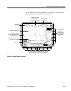
Tube Assembly