


Removal and Installation Procedures
6–32
TDS 684A, TDS 744A, & TDS 784A Service Manual
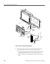
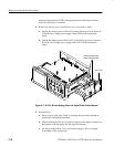
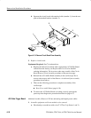
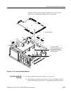
b. Separate the circuit board with attached cable (number 1), from the rear
plate with attached brackets (number 2).
1
2
3
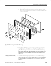
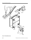
Figure 6–13: Remove Circuit Board From Assembly
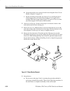
3. Replace circuit board:
Equipment Required: One
3
@
16
inch nutdriver.
a. Replace the failed circuit board with a replacement A23 SerPar Board
ordered from the factory (see Replaceable Parts List for detailed
ordering information). Do in reverse order steps a and b of the Circuit
Board Removal From Assembly procedure on the previous page.
b. Reinstall the A23 SerPar Board assembly in the oscilloscope. Do in
reverse order steps a and b of the Remove circuit board from assembly
procedure shown above.
c. Then see the following procedure to complete reassembly of the
oscilloscope:
H Rear Cover and Cabinet (page 6–18).
d. To ensure the A23 SerPar Board is working correctly, perform the
power-up short diagnostics procedure described on page 6–57.
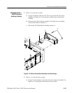
Additional modules Removed: D1 bus and analog-and digital-power cables.
1. Assemble equipment and locate modules to be removed
a. Have handy a screwdriver with a size T-15 TorxR tip (Items 1 and 2).
A29 Video Trigger Board