


Removal and Installation Procedures
6–40
TDS 684A, TDS 744A, & TDS 784A Service Manual
d. Do the procedure Front Cover, Trim Ring, Menu Buttons, and Attenuator
Panel (page 6–22)
2. Orient the oscilloscope: Set the oscilloscope so its top is down on the work
surface and its front is facing you.
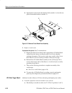
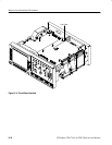
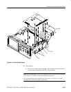
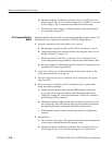
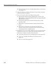
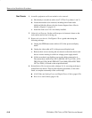
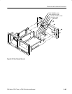
3. Remove the Acquisition Board: Use Figure 6–18 as a guide.
a. Disconnect the cables from (CH 3) SIGNAL OUT (at J1201), AUX
TRIG INPUT (at J1550), MAIN TRIG OUTPUT (at J1000), DELAYED
TRIG OUTPUT (at J1001).
b. If the option 05 video board is installed, disconnect the coax cable
attached to J1500.
c. Remove the six screws that mount the acquisition board to the main
chassis.
d. Remove the five front-panel screws that attach the frame to the
attenuator portion of the A10 Acquisition board. Lift the board away
from the main chassis to complete removal.
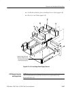
4. Reinstallation: Do, in reverse order, substeps 3a to 3d, reversing each step to
reinstall the acquisition board. Then see the following procedures, in the
order listed, to complete reassembly of the oscilloscope:
H A14 D1 Bus and Analog-Power and Digital-Power Cables (page 6–29).
H Front Cover, Trim Ring, Menu Buttons, and Attenuator Panel
(page 6–22).
H Rear Cover and Cabinet (page 6–18).