


Removal and Installation Procedures
6–48
TDS 684A, TDS 744A, & TDS 784A Service Manual
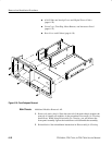
1. Assemble equipment and locate modules to be removed: Have handy a
screwdriver with a size T-15 TorxR
tip (Items 1 and 2). Locate the modules
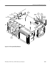
to be removed in the locator diagram Inner-Chassis Modules, Figure 6–2,
page 6–13.
2. Orient the oscilloscope: Set the oscilloscope so its bottom is down on the
work surface and its rear is facing you.
3. Remove the high-voltage fuse: If you are servicing this fuse, remove the fuse
from its fuse holder. Reverse the procedure to reinstall.
WARNING. Display tube handling: Use care when handling a display tube. If you
break a display tube it may implode, scattering glass fragments with high
velocity and possibly injuring you. Wear protective clothing, including safety
glasses (preferably a full-face shield). Avoiding striking the display tube with or
against any object.
Display tube storage: Store the display tube face down in a protected location,
placing it on a soft, nonabrasive surface to prevent scratching the face plate.
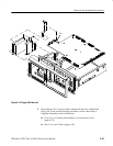
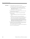
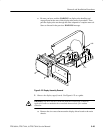
4. Remove the display tube:
a. Take the precautions outlined in the warning above. Reference Fig-
ure 6–22 while doing the following substeps.
b. Unplug the display tube connector from the back of the display tube and
the display tube yoke connector from the display circuit board (J170,
J305 and J570). Loosen the screw on the video board that holds the CRT
sockets. Then pull back on the video board slightly. This separates the
board from the socket.
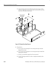
c. Remove the two screws that secure the band circling the front of display
tube to the front subpanel. Carefully guide display tube forward to
partially remove it from the front subpanel and to access the anode lead
connected to the display tube.
WARNING. High-voltage is present on the anode lead. Before unplugging the
anode in the following substep, you must discharge it: ground a flat-bladed
screwdriver (Item 5) with an insulated handle to the chassis through a suitable
grounding strap. Next, probe under the insulating cap of the anode lead and
touch the lead’s metal conductor to discharge. Repeat. After unplugging the
anode in substep d, touch its metal conductor to the chassis for a few minutes to
further ensure discharge.
d. Discharge the anode lead as described in the immediately proceeding
WARNING, unplug it from the display tube, and discharge that lead
(again see WARNING).