Using the Algorithms With C Code to Erase and Reprogram the ’F240
PRELIMINARY
A-52
PRELIMINARY
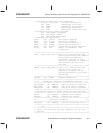
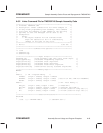
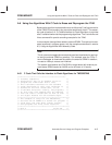
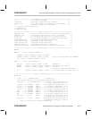
* Step 5. begin code that will initialize the ’240 registers *
*****************************************************************************
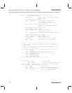
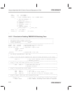
CLRC SXM ; Clear Sign Extension Mode
CLRC OVM ; Reset Overflow Mode
* Set Data Page pointer to page 1 of the peripheral frame
LDP #DP_PF1 ; Page DP_PF1 includes WET through EINT frames
* Clear system status register reset bits (PORRST, ILLADR, SWRST, & WDRST)
LACL #020h ; load mask pattern to clear rst flags
SACL SYSSR ; write ACC to SYSSR
* Set Watchdog timer period to 1 second
LACL #02Fh ; set WDCHK2 & 0 bits, WDCLK divider to max (1s)
SACL WDTCR ; write ACC out to WDTCR
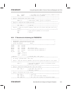
* Configure PLL for 4–MHz xtal, 10–MHz SYSCLK, and 20–MHz CPUCLK
* SPLK #00E4h,CKCR1 ;CLKIN(XTAL)=4 MHz,CPUCLK=20 MHz
* SPLK #00C3h,CKCR0 ;CLKMD=PLL Enable,SYSCLK=CPUCLK/2
* Configure PLL for 10–MHz osc, 10–MHz SYSCLK, and 20–MHz CPUCLK
SPLK #00B1h,CKCR1 ;CLKIN(OSC)=10 MHz,CPUCLK=20 MHz
SPLK #00C3h,CKCR0 ;CLKMD=PLL Enable,SYSCLK=CPUCLK/2
* Set VCCAON bit and CLKSRC1:0; leave other bits at their reset values.
SPLK #40C8h,SYSCR ; SYSCR <= 40C8h
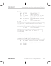
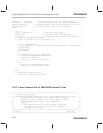
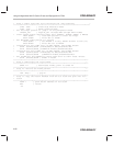
***************************************************************************
* Step 9. Deallocate the local frame *
***************************************************************************
SBRK 1+1 ; deallocate frame, point to saved FP
***************************************************************************
* Step 10. restore the frame pointer *
***************************************************************************
LAR AR0,*– ; pop FP
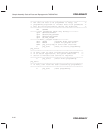
***************************************************************************
* Step 11. copy the return address from the s/w stack and push onto h/w *
* stack *
***************************************************************************
PSHD * ; push return address on h/w stack
RET ; return
.en


