


Operations that Modify the Contents of the ’F20x/F24x Flash Array
PRELIMINARY
2-4
PRELIMINARY
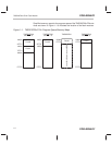
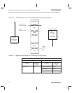
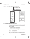
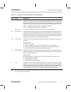
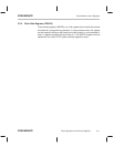
Figure 2–1. Flash Memory Logic Levels During Programming and Erasing
Erase operation
Depletion Mode
Logic 1
1 Margin
0 Margin
Logic 0
VER0
Erase
(Towards logic
Clear
Program
Flash Write
(Towards logic
Reference
level
Inverse Erase
Program operations
Reference Level
VER1
S
S
S
S
Reference Level
one level)
zero level)
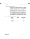
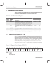
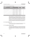
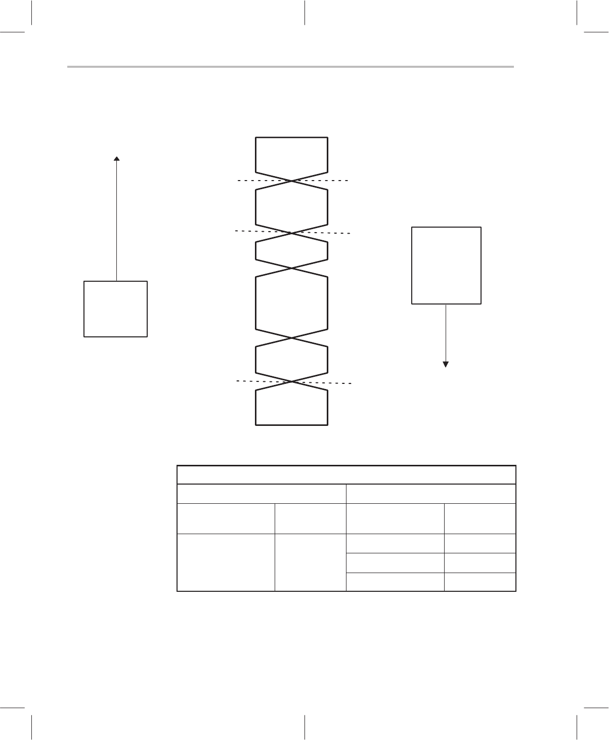
Table 2–1. Operations that Modify the Contents of the Flash Array
Change in Bit Level
Towards Logic 1 Towards Logic 0
Function Reference
Level
Function Reference
Level
Erase (all bits) VER1
Program (selected bits) VER0
Clear (all bits) VER0
Flash-Write (all bits) Inverse Erase