


Assembly Source for Algorithms
PRELIMINARY
A-17
Assembly Source Listings and Program Examples
PRELIMINARY
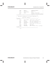
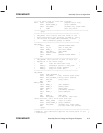
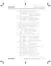
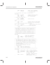
BCND FL_WRITE, NEQ ;If ACC<>0, then flwrite.
*Else, continue until until done with row.
BANZ NEXT_IVERS ;Loop 32 times.
SPLK #STOP,BASE_0 ;Flash STOP command.
CALL SET_MODE ;Disable flash commands.
;If here then test passed.
DONE RET ;Return to calling code.
* If here, then an error has occurred.
EXIT SPLK #1,ERROR ;Update error flag
SPLK #STOP,BASE_0 ;Flash STOP command.
CALL SET_MODE ;Disable flash commands.
CALL ARRAY ;ACCESS FLASH ARRAY
B DONE ;Get outa here.
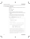
.page
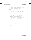
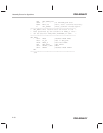
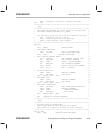
***************************************************
* FL_WRITE: This routine performs a fl_write on *
* the flash until a maximum is reached. The *
* array is defined by the variable FL_ST *
* and the segment(s) is defined by the PROTECT *
* mask. The following resources are used for *
* temporary storage: *
* AR0 Used for comparison *
* AR1 Used for pulse count (Global) *
* AR6 Parameter passed to DELAY *
* BASE_0 Parameter passed to SET_MODE *
* BASE_2 Used for flw cmd *
* BASE_3 Used for EXE + flw cmd *
***************************************************
FL_WRITE
SPLK #STOP,BASE_0 ;Flash STOP command.
CALL SET_MODE ;Disable flash commands.
LACL PROTECT ;Get sector_prot mask.
OR #FLWR ;Or in fl_write cmd.
SACL BASE_2 ;BASE_2 = fl_write cmd.
OR #FLWR_EX ;Or in EXE + fl_write cmd.
SACL BASE_3 ;BASE_3 = EXE + fl_write cmd.
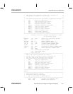
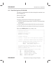
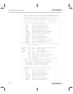
*Set the flash–write command.
CALL REGS ;Access flash regs.
LACC FL_ST ;ACC => SEG_CTL.
TBLW BASE_2 ;Initiate fl_write.
LAR AR6,#D10 ;Set delay.
CALL DELAY,*,AR6 ;Wait,10US flw stabilization time.
*Set the EXE bit (start flash–write pulse).
TBLW BASE_3 ;Start flw pulse.
LAR AR6,#D7K ;Set delay to 7 ms.
CALL DELAY,*,AR6 ;WAIT,7 ms.
LAR AR6,#D7K ;Set delay to 7 ms.
CALL DELAY,*,AR6 ;WAIT 7 ms.
*A 14–mS flash write pulse has been applied.
SPLK #STOP,BASE_0 ;Flash STOP command.
CALL SET_MODE ;Disable flash commands.
MAR *,AR1
MAR *+ ;Increment flw count.