Program Operation
PRELIMINARY
2-13
Flash Operations and Control Registers
PRELIMINARY
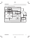
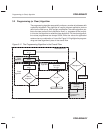
2.5 Program Operation
The program operation of the ’F20x/F24x flash module loads the application-
specific data (a pattern of 0s) into the flash array. The basis of the operation
is applying a program pulse to a single word of flash memory. The term
pro-
gram pulse
refers to the time during the program operation between the setting
and the clearing of the EXE bit ( bit 0 of SEG_CTR). During the program pulse,
charge is added to the addressed bits via the programming mechanism. Sev-
eral program pulses may be required to fully program the bits of a word, and
the application of program pulses is controlled by the programming algorithm.
The flash location to be programmed is specified by the address in the WADRS
register, and the data pattern to be programmed is loaded into the WDATA reg-
ister. Only the bits that contain a 0 are programmed; any bit positions contain-
ing a 1 remain unchanged. (See sections 2.3.3 and 2.3.4 for information about
how to load the WADRS and WDATA registers.)
To assure that the 0 bits are programmed with enough margin, the reads asso-
ciated with programming are performed using the VER0 read mode. After a
program pulse has been applied, the byte is read back in VER0 mode to assure
that programmed bits can be read as 0 over the entire operating range of the
device.
The flash module supports programming of up to eight bits of data. Therefore,
although the flash bits are addressed on 16-bit word boundaries, only eight bits
can be programmed at a time. The algorithm must limit the programming to
eight bits by masking the word to be programmed before writing it to the WDA-
TA register. For example, to mask off the upper byte while programming the
lower byte, the data value is logically 0Red with 0FF00h in software. When a
program pulse is applied, only the selected bits are programmed.


