


Index
PRELIMINARY
Index-1
PRELIMINARY
Index
A
access modes
code for changing A-25
array access 2-5, 2-10, 2-11, 2-16, 3-8
register access 2-5, 2-10, 2-11, 3-11
access–control register 2-5 to 2-7
modifying in TMS320F206 2-6
modifying in TMS320F24x 2-7
reading in TMS320F206 2-6
accessing the flash module 2-5
address complementing 3-11
algorithms
erase 3-10 to 3-13
flash–write 3-14 to 3-18
in the overall flow 3-2
limiting number of bits to be programmed 2-13
programming 3-4 to 3-9
applying a single erase pulse 3-11
applying a single flash–write pulse 3-15
applying a single program pulse 3-8
array protection 2-16
array segment locations 2-10
array size 1-3
array–access mode 2-5, 2-10, 2-11, 2-16, 3-8
See also
register–access mode
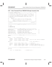
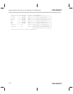
assembly source listings
algorithms, variables, and common subrou-
tines A-2 to A-26
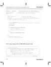
sample code for TMS320F206 A-32 to A-35
sample code for TMS320F240 A-40 to A-44
assistance from TI vii
B
basic concepts of flash memory 1-2
benefits of flash EEPROM 1-1, 1-5
block erase (flash erase) 1-2
boot loader code A-1
C
C source listings
code that calls the interface to the algo-
rithms A-37, A-47
disabling TMS320F240 watchdog timer A-50
initializing the TMS320F240 A-51
interface to flash algorithms A-27
C–callable interface to flash algorithms A-27
charge levels for progamming and erasing 2-4
charge margin.
See
margin
clear algorithm code (SCLR2x.ASM) A-5
clearing the array (clear operation) 2-14, 2-15
code origin for programming and erasing A-1
composition of flash module 1-3
control registers
accessing 2-5
described 2-5 to 2-12
D
data page pointer initialization A-2
data retention 1-2, 2-12
delay, in software (code listing) A-25
depletion mode
described 2-15
inverse–erase read mode 2-12
test and detection 2-12, 2-14, 3-15
devices with embedded flash EEPROM 1-3
E
embedded versus discrete flash memory 1-5
embedded flash memory described 1-1