


Operations that Modify the Contents of the ’F20x/F24x Flash Array
PRELIMINARY
2-3
Flash Operations and Control Registers
PRELIMINARY
This procedure is discussed in complete detail in Chapter 3.
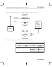
During these operations that are used to modify the contents of the flash array,
three special read modes, and a corresponding set of reference voltage levels,
are used when reading back data values to verify programming and erase op-
erations.
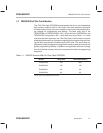
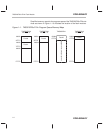
These read modes and reference levels are:
- VER0 – which is used to verify the logic zero level including margin,
- VER1 – which is used to verify the logic one level including margin, and
- Inverse Erase – which is used to verify depletion recovery.
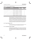
These concepts are illustrated graphically in Figure 2–1 and summarized in
Table 2–1.
Note that ONLY the Erase and the Flash-Write functions are truly “flash” in the
sense that these functions actually affect all bits in the array simultaneously.
In contrast, bit programming levels in the Program and Clear functions can be
controlled individually on a bit-by-bit basis.
Therefore, when using the Erase or Flash-Write functions, the whole array is
modified, and then the whole array is read, word by word, to verify whether all
words have reached the same value (if not, further iterations of the Erase or
Flash-Write functions continue).
In these cases, as mentioned previously, all the bits in the array are modified
simultaneously, but some bits may react more quickly, potentially resulting in
variation in actual levels on different bits. Therefore, when performing an
Erase, it is possible that some bits may reach depletion even before other bits
reach the logic one reference level (VER1).
The reason that it is critical to clear the array to a consistent zero level before
erasing the array is to give maximum immunity to depletion when erasing.
Note, however, that even when following this sequence, some flash arrays
may experience depletion, and may require recovery using the Flash-Write
function.
In contrast to the true “flash” operations Erase and Flash-Write, after each in-
cremental Program or Clear operation, each bit is tested against the VER0 ref-
erence level to determine the exact point at which it has reached the proper
value, following which, no further incremental adjustment of the level is made
on that bit. Therefore, when the Program or Clear operation is complete, all bits
are at the same zero level, which greatly increases proper data retention and
depletion immunity for the device. Again, note that the programming and erase
operations are discussed in complete detail in Chapter 3.