


Assembly Source for Algorithms
PRELIMINARY
A-12
PRELIMINARY
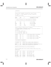
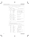
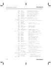
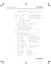
CLRC OVM ;Disable overflow mode.
LACL SEG_ST ;Get segment start address.
AND #04000h ;Get array start address.
SACL FL_ST ;Save array start address.
OR #03FFFh ;Get array end address.
SACL FL_END ;Save array end address.
SPLK #0,ERROR ;Reset error flag
LAR AR1,#0 ;Set erase count to 0.
SPLK #STOP, BASE_0 ;Stop command.
CALL SET_MODE ;Disable any flash cmds.
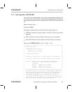
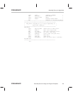
XOR_ERASE
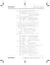
** Compute checksum for flash, using address complementing.**
LACC SEG_END
SUB SEG_ST
SAC BASE_4 ;Segment length–1.
LAR AR2,BASE_4 ;load n–1 to loop n times.
ADD #1
SACL BASE_4 ;Segment length.
SPLK #VER1,BASE_0 ;VER1 command.
CALL SET_MODE ;Set VER1 mode.
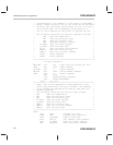
MAR *,AR2
BLDD #SEG_ST,BASE_1 ;Segment start address.
SPLK #0,BASE_3 ;Clear checksum.
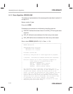
RD1_LOOP ;For I = SEG_ST to SEG_END.
LACC BASE_1 ;ACC => CURRENT ADDR.
XOR FL_END ;XOR addr with flash end addr.
TBLR BASE_2 ;Dummy Read.
LACC BASE_1 ;Get actual addr again.
TBLR BASE_2 ;True Read.
ADD #1 ;Increment flash addr.
SACL BASE_1 ;Store for next read.
LACC BASE_3 ;Get old check sum.
ADD BASE_2 ;ACC=>ACC+FL_DATA.
SACL BASE_3 ;Save new check sum.
BANZ RD1_LOOP,*–
ADD BASE_4 ;Should make ACC = 0 for
;erased array.
BCND XOR_ERFIN,EQ ;If BASE_3 = 0, finished.
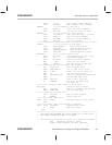
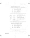
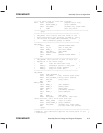
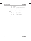
***** If not erased, apply an erase pulse.
CALL ERASE_A ;Else, pulse it again.
MAR *,AR1 ;ARP–>AR1 (Erase pulse count)
MAR *+ ;Increment Erase count.
LAR AR0,#MAX_ER
CMPR2 ;If AR1>MAX_ER then
BCND EXIT,TC ;fail, don’t continue erasing.
B XOR_ERASE ;Else, check again.
***** If here, then erase passed; now check for depletion.
XOR_ERFIN
SPLK #STOP, BASE_0 ;Stop command.
CALL SET_MODE ;Disable any flash cmds.
CALL INV_ERASE ;Check for depletion.
DONE RET ;Return to calling code.