


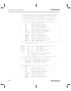


Assembly Source for Algorithms
PRELIMINARY
A-16
PRELIMINARY
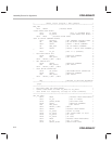
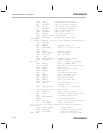
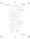
* BASE_3 Used for EXE + flw cmd *
**************************************************************
.include ”svar20.h” ;defines variables for flash0
;or for flash1 array
*
MAX_FLW .set 10000 ;Allow only 10000 flw pulses.
INV_ER .set 018h ;INVERSE ERASE COMMAND WORD
FLWR .set 6 ;FLASH WRITE COMMAND WORD
FLWR_EX .set 047h ;FLASH WRITE EXEBIN COMMAND WORD
STOP .set 0 ;RESET REGISTER COMMAND WORD
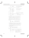
.def FLWS
.ref PROTECT,SEG_ST,SEG_END
.ref DELAY,REGS,ARRAY
.sect ”fl_wrt”
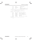
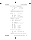
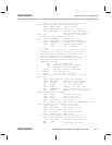
******************************************************
* FLWS: This routine is used to check for bits *
* in depletion mode. If any are found, flash– *
* write is used to recover. *
* AR1 Flash–write pulse count. *
* AR2 Used for main banz loop. *
* BASE_0 Parameter passed to Set_mode. *
* BASE_1 Used for flash address. *
* BASE_2 Used for flash data. *
******************************************************
FLWS:
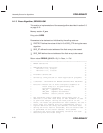
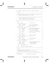
******************************************************
* Code initialization section *
* Initialize test loop counters: *
* AR1 is the number of flash–write pulses. *
******************************************************
SETC INTM ;Disable maskable ints.
LACL SEG_ST ;Get segment start address.
AND #04000h ;Get array start address.
SACL FL_ST ;Save array start address.
SPLK #0,ERROR ;Reset error flag.
LAR AR1,#0 ;Set FLW count to 0.
SPLK #STOP,BASE_0 ;Flash STOP command.
CALL SET_MODE ;Disable any flash commands.
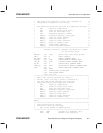
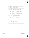
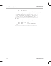
INV_ERASE
SPLK #INV_ER,BASE_0
CALL SET_MODE ;Set inverse–erase mode.
BLDD #FL_ST,BASE_1 ;Array start address.
LAR AR2,#31 ;Loop count.
MAR *,AR2
NEXT_IVERS
LACL BASE_1 ;Get address.
TBLR BASE_2 ;Dummy read.
TBLR BASE_2 ;Dummy read.
TBLR BASE_2 ;Read data.
ADD #1 ;Increment address.
SACL BASE_1 ;Save address.
ZAC
ADD BASE_2 ;Add data.