


99
ICC
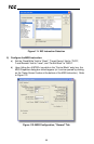
c) In this example, we will be reading a total of 25 registers beginning at
N10:11 (register 11, the drive’s “deceleration time 1” parameter). To
configure this, under “This Controller” set the “Data Table Address” field to
N18:11, set the “Size in Elements field” to 25, and set the “Channel” field to
1 (Ethernet).
d) Under “Target Device”, set the “Data Table Address” field to N10:11
(starting target register=11) and set the “MultiHop” field to Yes to cause the
“MultiHop” tab to appear.
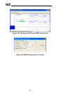
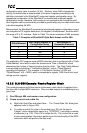
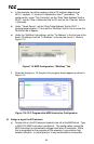
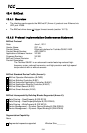
e) Under the “MultiHop” tab settings, set the “To Address” in the first row to the
drive’s IP address, and the “To Address” in the second row to 0. Refer to
Figure 113.
Figure 113: MSG Configuration, "MultiHop" Tab
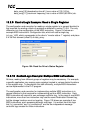
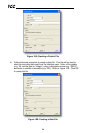
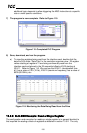
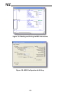
f) Close the dialog box. At this point, the program should appear as shown in
Figure 114.
Figure 114: PLC Program after MSG Instruction Configuration
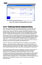
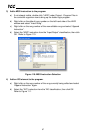
6) Assign a tag to the XIO element.
a) Double-click on the XIO element located to the left of the MSG block. Type
in N20:0/15 (MSG instruction’s enable bit). This configuration causes the
MSG instruction to automatically retrigger itself when it completes. While
this is acceptable for the purposes of this example, it can produce high
network utilization. In actual practice, it may be desirable to incorporate