


71
ICC
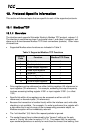
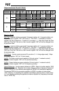
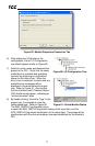
Output Instances 20 and 21 Detail
Instance Byte
Bit
7
Bit
6
Bit
5
Bit
4
Bit
3
Bit
2
Bit
1
Bit
0
20
0
Fault
Reset
Run
Fwd
1
2 Speed Reference (Low Byte)
3 Speed Reference (High Byte)
21
0
NetRef NetCtrl
Fault
Reset
Run
Rev
Run
Fwd
1
2 Speed Reference (Low Byte)
3 Speed Reference (High Byte)
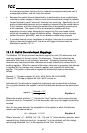
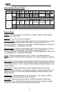
Mapping Detail
Run Fwd: forward rotation command (0=forward rotation off, 1=forward rotation on).
Maps to inverter register 1007, bits 9 and 10. Run Fwd = 1 translates to inverter
register 1007 bit 9 (direction) = 0 and bit 10 (run/stop) = 1. Note that if both the “Run
Fwd” and “Run Rev” bits are on, then inverter register 1007 will not be changed from
its previous value.
Run Rev: reverse rotation command (0=reverse rotation off, 1=reverse rotation on).
Maps to inverter register 1007, bits 9 and 10. Run Rev = 1 translates to inverter
register 1007 bit 9 (direction) = 1 and bit 10 (run/stop) = 1. Note that if both the “Run
Fwd” and “Run Rev” bits are on, then inverter register 1007 will not be changed from
its previous value.
Fault Reset: Inverter reset command (0=no action, 0→1 rising edge=reset). Maps
to inverter register 1007, bit 13 (fault reset).
NetCtrl: Run/stop control source selection (0=local control, 1=network control).
Maps to inverter register 1007, bit 15 (command priority).
NetRef: Speed reference source selection (0=local control, 1=network control).
Maps to inverter register 1007, bit 14 (frequency priority).
Speed Reference: Inverter speed reference in RPM. Maps to inverter register 1008
(frequency command). Because the inverter always requires a frequency command
value in units of Hz, the interface card applies an RPM-to-Hz conversion equation.
The general RPM-to-Hz conversion equation is [RPM x number of motor poles /
120]. However, for simplicity the interface card always assumes that a 4-pole motor
is in use, thereby reducing the applied conversion equation to [frequency command
value = RPM / 30].