


75
ICC
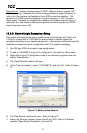
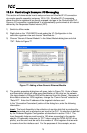
13.2.4 ControlLogix Example: I/O Messaging
This section will demonstrate how to setup and use an EtherNet/IP I/O connection
via vendor-specific assembly instances 100 & 150. EtherNet/IP I/O messaging
allows the drive’s registers to be directly mapped into tags in the ControlLogix PLC.
Once an I/O connection is established, it is automatically synchronized at an interval
defined by the Requested Packet Interval (RPI).
1) Switch to offline mode.
2) Right click on the 1756-ENBT/A node under the I/O Configuration in the
controller organizer view and choose “New Module…”
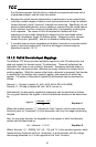
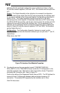
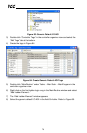
3) Choose “Generic Ethernet Module” in the Select Module dialog box and click
“OK”. Refer to Figure 77.
Figure 77: Adding a New Generic Ethernet Module
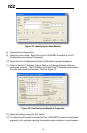
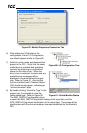
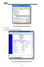
4) The module properties dialog box will open (refer to Figure 78). Enter a Name
and Description which will allow easy identification of the drive on the network
(the tags created in RSLogix 5000 will be derived from this Name). Because all
drive data is stored as 16-bit registers, change the “Comm Format” selection to
“Data-INT”. Enter the IP address of the targeted interface card.
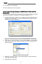
In the “Connection Parameters” portion of the dialog box, enter the following
information:
Input: The Input Assembly is the collection of monitor data that is produced by
the interface card and is received as an input to the PLC. Its structure is defined
by the Produced Register Configuration as described in section 10.8.4. The
Input Assembly Instance must be set to 150 when connecting to the vendor-
specific I/O assembly instances (or 70/71 when using the ODVA AC/DC drive
profile), and the size must be set to the number of 16-bit registers that we wish
to receive from the interface card. For the purposes of this example, we are